DTXTREME
Ⅲ
18
DIMM Installation
1
Turn the DTXTREME
Ⅲ
power off, and disconnect
the power cord.
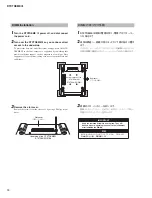
2
Turn over the DTXTREME
Ⅲ
so you canhave direct
access to the underside.
To protect the data dial and sliders from damage, place the DTX-
TREME
Ⅲ
so the four corners are supported by something that
provides suf
fi
cient support, such as magazines or cushions. Place
supports at all four corners, taking care not to touch the Data dial
and Sliders.
3
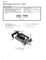
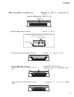
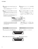
Remove the slot cover.
Remove the screws from the slot cover by using a Phillips screw-
driver.
Rear panel
(リアパネル面)
Bottom surface of the
DTXTREME
Ⅲ
(DTXTREME
Ⅲ
底面)
重要
外したネジはなくさないようにしてください。このネジは、
DIMM取り付け後、再度使用します。
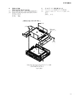
Slot cover
(スロットカバー)
Underside of the DTXTREME
Ⅲ
(DTXTREME
Ⅲ
底面)
IMPORTANT
Keep the removed screws in a safe place. They will
be used when re-attaching the cover to the instrument
after installing the DIMMs.
DIMM の取り付け手順
1
DTXTREME
Ⅲ
本体の電源を切り、電源アダプターコー
ドを抜きます。
2
本体を裏返し、底面が見えるように下図の向きに置き
ます。
このとき、データダイアルやスライダーを破損しないように
本体の四隅に雑誌などをクッションにしてその上に乗せます。
3
底面のスロットカバーを外します。
底面のスロットカバー止めネジ 2 本をドライバーで外し、
本体よりスロットカバーを外します。
Summary of Contents for DTXTREME III
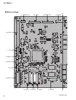
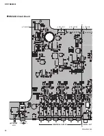
Page 30: ...DTXTREMEⅢ 30 B B DM Circuit Board 2NA WJ91030 2 ...
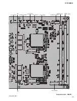
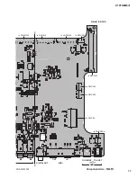
Page 31: ...31 DTXTREMEⅢ B B Pattern side パターン側 2NA WJ91030 2 ...
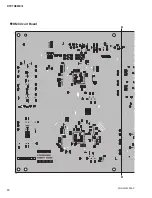
Page 34: ...DTXTREMEⅢ 34 D D DMSUB Circuit Board 2NA WJ91040 ...
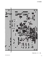
Page 35: ...35 DTXTREMEⅢ D D Pattern side パターン側 Scale 85 100 2NA WJ91040 ...
Page 38: ...DTXTREMEⅢ 38 F F JK Circuit Board 2NA WJ91050 2 ...
Page 39: ...39 DTXTREMEⅢ F F Pattern side パターン側 Scale 95 100 2NA WJ91050 2 ...
Page 42: ...DTXTREMEⅢ 42 H H or D PN Circuit Board 2NA WJ91060 2 ...
Page 43: ...43 DTXTREMEⅢ H H Pattern side パターン側 Scale 80 100 2NA WJ91060 2 ...

