27
DTXTREME
Ⅲ
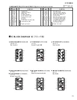
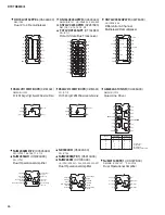
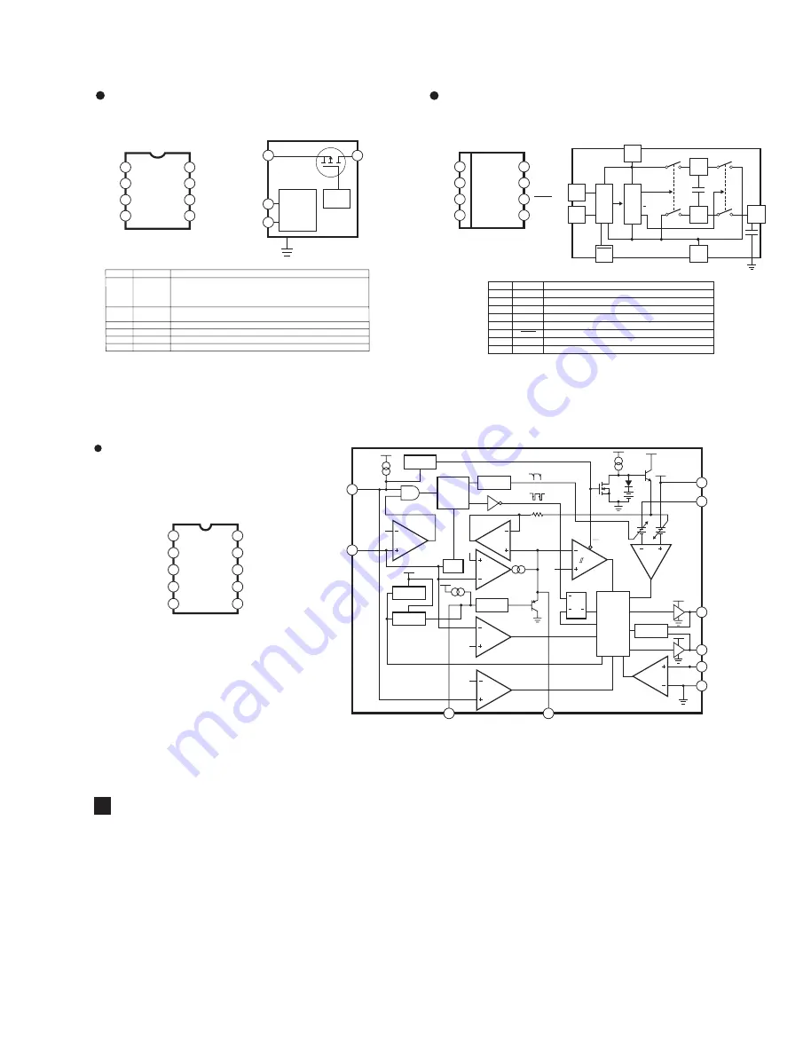
LTC1773EMS
(X3215A00)
DC-DC CONVERTER
I
TH
1
RUN/SS
2
SYNC/FCB
3
V
FB
4
GND
5
SW
10
SENSE –
9
V
IN
8
TG
7
BG
6
BURST
DEFEAT
0.4
μ
A
1.5
μ
A
0.6V
OSC
FREQ
SHIFT
0.8V REF
UVLO
TRIP = 2.5V
SYNC
DEFEAT
X
Y
Y= “0” ONLY WHEN X IN A CONSTANT “1”
SLOPE
COMP
3
SYNC/FCB
4
V
FB
2
RUN/SS
1
I
TH
8
V
IN
0.8V
SYNC
DEFEAT
0.22V
50mV
EN
SLEEP
0.4V
BURST
COMP
0.86V
OVDET
0.8V
EA
I
RCMP
I
COMP
UVLO
TRIP = 2.5V
SHUTDOWN
S
Q
R
Q
SWITCHING
LOGIC
AND
BLANKING
CIRCUIT
ANTI
SHOOT-THRU
9
SENSE –
7
TG
6
BG
10
SW
5
GND
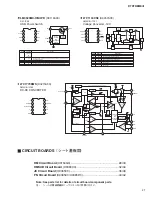
LM3525MX-H/NOPB
(X3119A00)
USB Power Switch
1
2
3
4
8
7
6
5
EN
NC
FLAG
GND
OUT
NC
IN
OUT
1
EN
2
FLAG
7
IN
Error
Detect
and
Shutdown
Control
8
OUT
FET
Drive
Pin No.
1
2
3
4, 5
7
6, 8
Pin Name
EN
(LM3525-L)
EN
(LM3525-H)
FLG
GND
NC
IN
OUT
Pin Function
Enable (Input): Logic-compatible enable input.
Fault Flag (Output): Active-low, open-drain output. Indicates overcurrent, UVLO,
and thermal shutdown.
Ground
Not internally connected.
Supply Input: Input to the power switch and the supply voltage for the IC.
Switch Output: Output of the high side switch. Pins 6 and 8 must be tied together.
LTC1144CS8
(X9457A00)
Voltage Converter -12V
1
2
3
4
8
7
6
5
BOOST
CAP
-
CAP
+
GND
V
+
V
OUT
OSC
SHDN
Pin No.
1
2
3
4
6
5
7
8
Pin Name
BOOST
CAP+
GND
CAP-
VOUT
SHDN
OSC
V+
Pin Function
This pin will raise the oscillator frequency by a factor of 10 tied high.
Positive Terminal for Pump Capacitor
Ground Reference
Negative Terminal for Pump Capacitor
Output of the Converter
Shutdown Pin
Oscillator Input Pin
Input Voltage
OSC
÷
2
SW1
C2
C1
+
+
φ
φ
SHDN
(6)
OSC
(7)
10X
(1)
V+
(8)
CAP+
(2)
CAP-
(4)
GND
(3)
V
OUT
(5)
BOOST
SW2
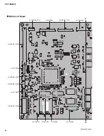
CIRCUIT BOARDS
(シート基板図)
(X3164G0) ............................................................... 28/30
(X9380C0) ....................................................... 32/34
(X9365C0) ................................................................ 36/38
(X9385C0/X9385D0) ............................................... 40/42
Note: See parts list for details of circuit board component parts.
注 :
シートの部品詳細はパーツリストをご参照ください。
Summary of Contents for DTXTREME III
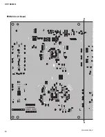
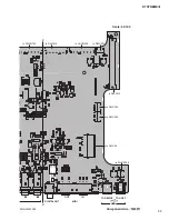
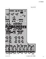
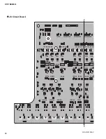
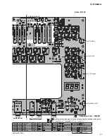
Page 30: ...DTXTREMEⅢ 30 B B DM Circuit Board 2NA WJ91030 2 ...
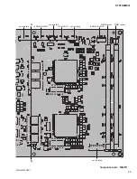
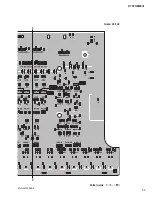
Page 31: ...31 DTXTREMEⅢ B B Pattern side パターン側 2NA WJ91030 2 ...
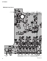
Page 34: ...DTXTREMEⅢ 34 D D DMSUB Circuit Board 2NA WJ91040 ...
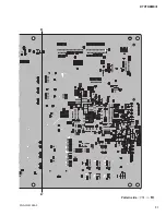
Page 35: ...35 DTXTREMEⅢ D D Pattern side パターン側 Scale 85 100 2NA WJ91040 ...
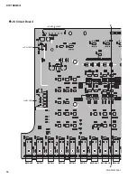
Page 38: ...DTXTREMEⅢ 38 F F JK Circuit Board 2NA WJ91050 2 ...
Page 39: ...39 DTXTREMEⅢ F F Pattern side パターン側 Scale 95 100 2NA WJ91050 2 ...
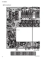
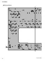
Page 42: ...DTXTREMEⅢ 42 H H or D PN Circuit Board 2NA WJ91060 2 ...
Page 43: ...43 DTXTREMEⅢ H H Pattern side パターン側 Scale 80 100 2NA WJ91060 2 ...

