7
DTXTREME
Ⅲ
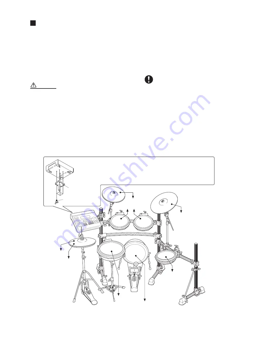
CONNECTING THE PADS
(パッドの接続)
PCY135
DTXTREME
Ⅲ
PCY155
KP125
TP120SD
RHH135
TP100
TP100
TP100
to
4
TOM1
to HI-HAT
CONTROL
*
Foot pedal is not included
in the Standard Set.
*
フットペダルはスタンダード
セットには含まれません。
to
)
TOM2
to
2
CRASH
to
6
RIDE
to
0
TOM3
to
KICK
/
to
/
SNARE
to
-
HI-HAT
Holder
(モジュールホルダー )
(included
(付属品)
)
Wing Bolt
(ちょうボルト)
x 4 (included
(付属品)
)
DTXTREME
Ⅲ
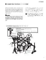
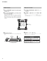
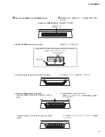
Attaching the holder
Attach the included holder to the DTXTREME
Ⅲ
using the wing bolts.
*
Be sure to use the included screws.
DTXTREME
Ⅲ
の取り付け
DTXTREME
Ⅲ
に付属のモジュールホルダーとちょうボルトを使って、左図のように取り付けます。
*
必ず付属の止めネジを使用してください。
●
DTXTREME
Ⅲ
Standard Set
(スタンダードセット)
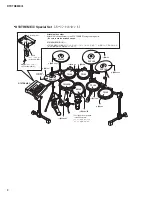
Referring to the illustration below or next page, connect
the output cable from each pad to each Trigger Input jack
located on the rear panel of the DTXTREME
Ⅲ
. All Trigger
Input jacks are conveniently labeled (
q
SNARE, etc.), so
make sure each pad is connected to its corresponding
Trigger Input jack.
WARNING
• To prevent electric shock and damage to the devi-
ces, make sure the power is switched OFF on the
DTXTREME
Ⅲ
and all related devices before making any
connections to the DTXTREME
Ⅲ
’s input and output
jacks.
下の図または次ページの図を参考に、各パッドからの出
力ケーブルを DTXTREME
Ⅲ
リアパネルの各トリガー入
力端子へ接続します。各トリガー入力端子には、それぞ
れ接続するパッドの名称が「
q
SNARE」などと印刷され
ていますので、該当するパッドを接続します。
・DTXTREME
Ⅲ
の入出力端子にケーブルを接続
する際は、感電と機器の損傷を防ぐため、必ず
DTXTREME
Ⅲ
および各機器の電源を切った状態
で行なってください。
Summary of Contents for DTXTREME III
Page 30: ...DTXTREMEⅢ 30 B B DM Circuit Board 2NA WJ91030 2 ...
Page 31: ...31 DTXTREMEⅢ B B Pattern side パターン側 2NA WJ91030 2 ...
Page 34: ...DTXTREMEⅢ 34 D D DMSUB Circuit Board 2NA WJ91040 ...
Page 35: ...35 DTXTREMEⅢ D D Pattern side パターン側 Scale 85 100 2NA WJ91040 ...
Page 38: ...DTXTREMEⅢ 38 F F JK Circuit Board 2NA WJ91050 2 ...
Page 39: ...39 DTXTREMEⅢ F F Pattern side パターン側 Scale 95 100 2NA WJ91050 2 ...
Page 42: ...DTXTREMEⅢ 42 H H or D PN Circuit Board 2NA WJ91060 2 ...
Page 43: ...43 DTXTREMEⅢ H H Pattern side パターン側 Scale 80 100 2NA WJ91060 2 ...


