DTXTREME
Ⅲ
94
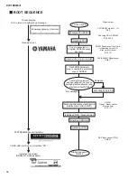
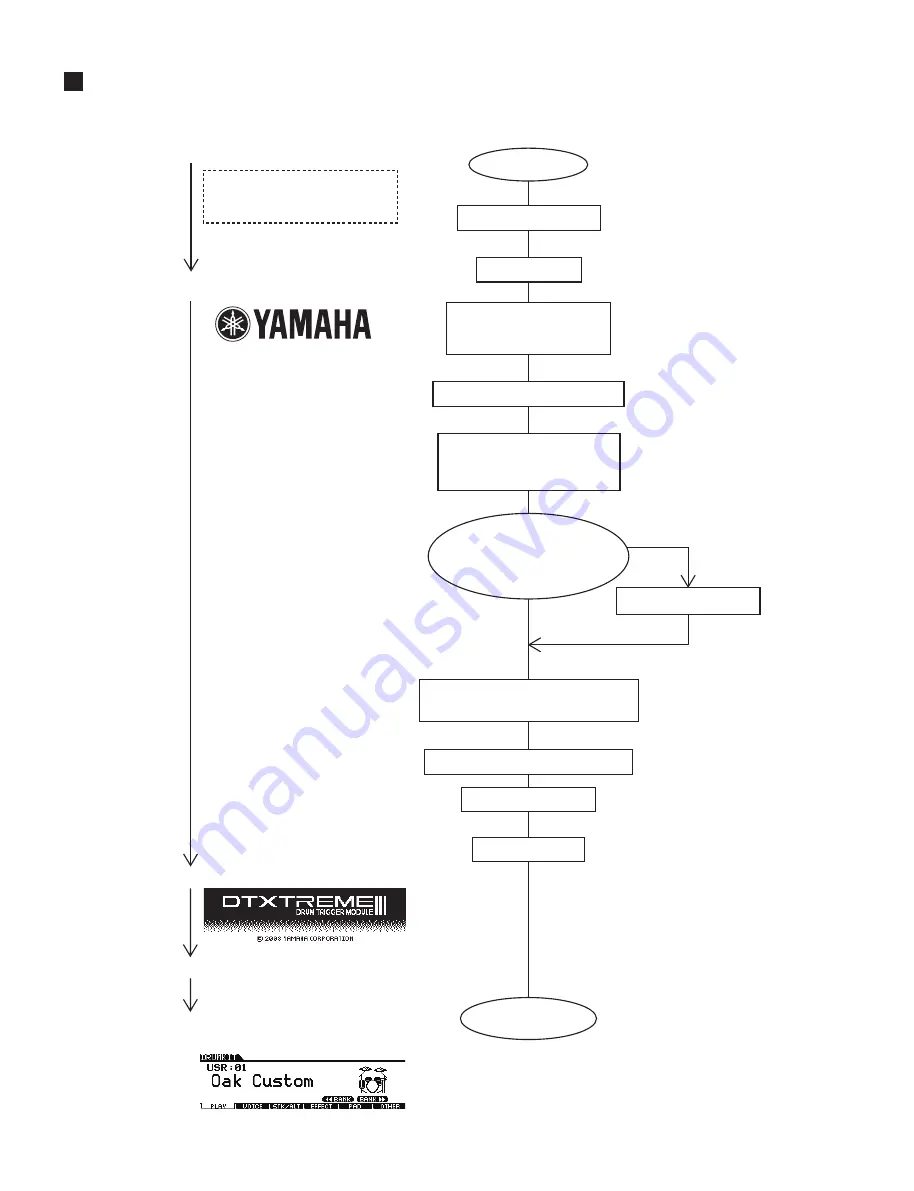
BOOT SEQUENCE
Screen display
No message appears on the screen
LCD is turned on without any message
Opening screen
DTXTREME
Ⅲ
banner indication
7-SEG LED is turned on to indicate “P01”
Indicates Top screen
(DRUM KIT mode appears)
Turns on power
Canceling CPU RESET
Initializing CPU
Copy is executed on
Program SDRAM except
boot area
Normal mode program is started
Flash ROM parameter
area is copied to parameter
area of SDRAM
Checking for parameter
damage (judgment is based on
damage presence/absence judg-
ment data in flash ROM)
Damaged
Not damaged
Executing Factory Set
Executing initialization of each device
(USB(Function), MIDI, SWP51)
Initializing SWP51 (Tone generator)
Initializing USB Host
Initializing LCDC
Startup sequence
finished
Signal output
CPU RESET signal L
→
H
IC6
‑
4
Checking CS of SDRAM
IC29,30-19
SWP51 Reset cancel (First time)
(for detecting Switch ON
at the time of startup)
IC25-111
DAC(AK4393) Reset cancel
CN6-11
SWP51
Reset
〜
Reset cancel
(Second time)
IC25-111
DAC Mute cancel (PTJ5)
CN6-27
Summary of Contents for DTXTREME III
Page 30: ...DTXTREMEⅢ 30 B B DM Circuit Board 2NA WJ91030 2 ...
Page 31: ...31 DTXTREMEⅢ B B Pattern side パターン側 2NA WJ91030 2 ...
Page 34: ...DTXTREMEⅢ 34 D D DMSUB Circuit Board 2NA WJ91040 ...
Page 35: ...35 DTXTREMEⅢ D D Pattern side パターン側 Scale 85 100 2NA WJ91040 ...
Page 38: ...DTXTREMEⅢ 38 F F JK Circuit Board 2NA WJ91050 2 ...
Page 39: ...39 DTXTREMEⅢ F F Pattern side パターン側 Scale 95 100 2NA WJ91050 2 ...
Page 42: ...DTXTREMEⅢ 42 H H or D PN Circuit Board 2NA WJ91060 2 ...
Page 43: ...43 DTXTREMEⅢ H H Pattern side パターン側 Scale 80 100 2NA WJ91060 2 ...

