background image

DVD-S510/DV-S5350

30

XXX

MXXxxx

1

2

3

4

5

6

7

8

9

10

11

12

13

14

15

16

48

47

46

45

44

43

42

41

40

39

38

37

36

35

34

33

17

18

19

20

21

22

23

24

25

26

27

28

29

30

31

32

64

63

62

61

60

59

58

57

56

55

54

53

52

51

50

49

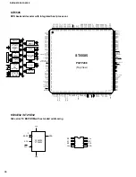
NEW

CD-A

CD-C

CD-B

CD-D

CD-REF

CD-E

CD-F

VDDA1

VSSA1

DVD-MI

-

DVD-A

DVD-B

DVD-C

DVD-D

DVD-REF

TM

VSSD

COP

COM

COO

VDDD5

STB

-

LAND

HEADER

VDDD3

SIDA

SICL

SILD

-

-

FTC

TDO

TD1

FTC-REF

TD2

LPF-DPD1

LPF-DPD2

O-CENTRAL

S2

S1

VSSA4

VDDA4

O-D

O-C

O-B

O-A

VDDA3

VSSA3

CD-LO

R-EXT

VDDA2

VSSA2

DVD-LO

RFN

RFP

RF-REF

VDDL

CD-MI

-

-

-

-

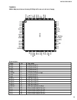
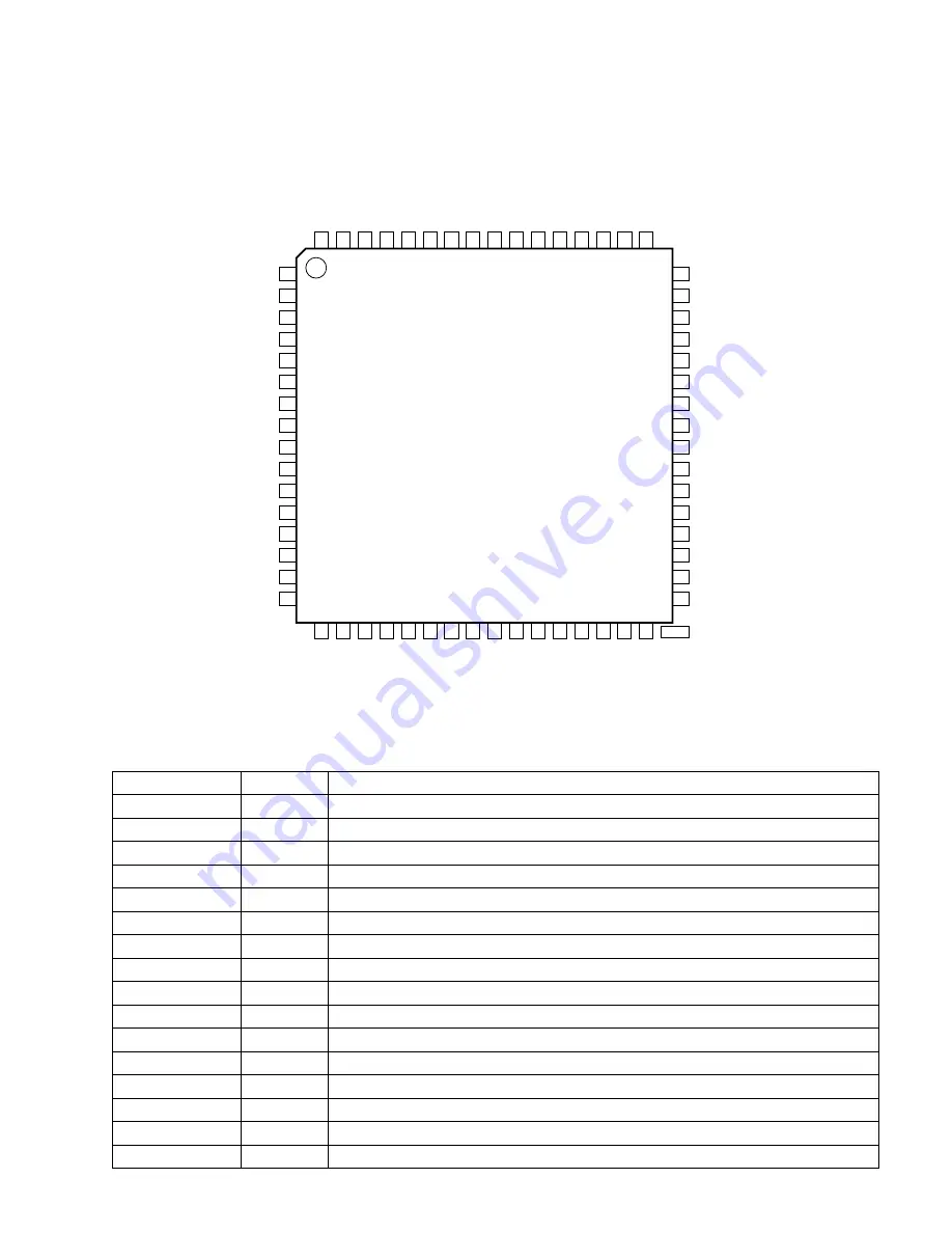
TZA1023

TZA1033

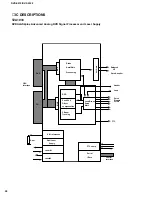
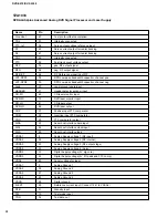
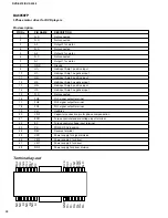
DVDALAS2plus Advanced Analog DVD Signal Processor and Laser Supply

Pin description

Name

Pin

Description

CD-A

1

CD pick up input A

CD-B

2

CD pick up input B

CD-C

3

CD pick up input C

CD-D

4

CD pick up input D

CD-REF

5

CD pick up reference voltage

CD-E

6

CD pick up input E

CD-F

7

CD pick up input F

DVD-A

12

DVD pick up input A

DVD-B

13

DVD pick up input B

DVD-C

14

DVD pick up input C

DVD-D

15

DVD pick up input D

DVD-ref

16

DVD pick up reference voltage

O-A

48

Servo current output for Focus-A

O-B

47

Servo current output for Focus-B

O-C

46

Servo current output for Focus-C

O-D

45

Servo current output for Focus-D

Summary of Contents for DV-S5350

Page 1: ...nsive components and failure of the product to perform as specified For these reasons we advise all YAMAHA product owners that any service required should be performed by an authorized YAMAHA Retailer or the appointed service representative IMPORTANT The presentation or sale of this manual to any individual or firm does not constitute authorization certification or recognition of any applicable te...

Page 2: ...rocedures other than those specified herein may result in hazardous radiation exposure Laser Emitting conditions 1 When the Top Cover is removed and the POWER SW is turned to the ON position the laser component will emit a beam for several seconds to detect if a disc is present During this time 5 10 sec the laser may radiate through the lens of the laser pick up unit Do not attempt any servicing d...

Page 3: ...NÅR DEKSEL ÅPNES UNNGÅ EKSPONERING FOR STRÅLEN VARNING SYNLIG OCH OSYNLIG LASERSTRÅLNING NÄR DENNA DEL ÄR ÖPPNAD BETRAKTA EJ STRÅLEN VARO AVATT AESSA OLET ALTTIINA NÄKYVÄLLE JA NÄKYMÄTTÖMÄLLE LASER SÄTEILYLLE ÄLÄ KATSO SÄTEESEEN VORSICHT SICHTBARE UND UNSICHTBARE LASERSTRAHLUNG WENN ABDECKUNG GEÖFFNET NICHT DEM STRAHL AUSSETSEN DANGER VISIBLE AND INVISIBLE LASER RADIATI ON WHEN OPEN AVOID DIRECT E...

Page 4: ...it assembly into which the device will be installed CAUTION Be sure no power is applied to the chassis or circuit and observe all other safety precautions 8 Minimize bodily motions when handling unpackaged replacement ES devices Otherwise harmless motion such as the brushing together of your clothes fabric or the lifting of your foot from a carpeted floor can generate static electricity ESD suffic...

Page 5: ...DVD S510 DV S5350 4 FRONT PANELS DVD S510 DV S5350 REMOTE CONTROL TRANSMITTER ...

Page 6: ...DVD S510 DV S5350 5 REAR PANELS DVD S510 B G models DVD S510 U C models DVD S510 A model DVD S510 R model DVD S510 T model DV S5350 U model ...

Page 7: ...output Cinch white red x2 U C A R T Digital Output 1 coaxial 1 optical IEC958 for CDDA LPCM IEC1937 for MPEG1 2 AC 3 and DTS GENERAL Dimensions w x h x d 435 x 91 x 314 mm Weight Approx 3 3 Kg Finish Black color U C A B G Gold color R G T Titan color G Power supply 120 V 60 Hz U 230 V 50 Hz B G 240 V 50 Hz A 110 120 220 240 V 50 60 Hz R 220 V 50 Hz T Power consumption 20 W Standby mode 5 W B G 3 W...

Page 8: ...ully flex connection to OPU and wire connection to tray motor demount board 2 7 mm for screws with 33 35 and 36 1 7 mm for removing MONO board 18 2 from DVD Mechanism 18 1 7 TruSurround and the SRS symbol are trademarks of SRS Labs Inc TruSurround technology is manufactured under license from SRS Labs Inc Manufactured under license from Dolby Laboratories Dolby and the double D symbol are trademar...

Page 9: ... left side of the tray by pulling it forward 2 Fig 2 3 While lifting up the tray 3 remove the tray by pulling it forward 4 Fig 2 Fig 1 Fig 2 SERVICE HINTS Diagnostic software In chapter Diagnostic software some tests are refering to the SCART functionality These tests are for sets with RGB output For sets without RGB output no SCART connector is mounted In these sets the SCART tests will automatic...

Page 10: ...ipt executes all diagnostic nuclei that do not need any user interaction and are meaningful on a standalone DVD player The nuclei called in the dealer script are the following the number after each nucleus name corresponds with the number being on the local display when the nucleus is executed during the dealer script Nucleus Description VideoColSetupComm 9 Checks the I2C interface with the RGB vi...

Page 11: ... check results of certain nuclei the player script expects some interaction of the user i e to approve a test picture or a test sound Some nuclei e g nuclei that test functionality of the Basic Engine module require that the DVD player itself is opened to enable the user to observe moving parts and approve their movement visually Only tests within the scope of the diagnostic software will be execu...

Page 12: ...local keyboard once The code of the key pressed is shown on the local display 1 hexadecimal digit immediately followed by a hexadecimal number indicating how many times that key has been pressed Example of the local display during this test Figure 2 The key codes displayed on the local display will scroll from right to left when the display gets full the text tb will remain on display key id key 0...

Page 13: ...TLES 4B SUBTITLE ON OFF E3 ROOT MENU 54 TITLE MENU 71 MENU D1 SETUP MENU 82 ON SCREEN F RETURN 83 RESUME D7 SCAN 2A SHUFFLE 1C REPEAT 1D A B REPEAT 3B TOGGLE SCART 43 OPEN CLOSE 42 FTS FB KARAOKE E4 OPTION FA ZOOM F7 Figure 7 After pressing NEXT the result of the remote control test is displayed on the local display of the DVD player as follows Figure 8 Or Figure 9 Pressing NEXT on the local keybo...

Page 14: ...e result of this test will be TRUE sound ok 3 BASIC ENGINE note Basic engine means DVD mechanism 3 1 VERSION NUMBER In the basic engine tests the version number of the Basic Engine will be shown first as the following example Figure 15 By pressing the NEXT key the Basic Engine tests are started 3 2 TRAY TEST First the tray is tested The purpose of this test is also to give the user the opportunity...

Page 15: ...pressing PAUSE indicates the function does not work Pressing NEXT proceeds to the next test after a reset of the radial nucleus BeRadialOff If the user presses NEXT before pressing PLAY or PAUSE the result of this test will be TRUE radial successful 3 7 JUMP TEST listening test The sixth and last Basic Engine test tests the jumping by calling nuclei BeGroovesIn BeGroovesMid and BeGroovesOut During...

Page 16: ...ng NEXT the user can continue to the next test See table below Error log bits table Read ERROR LOG Read ERROR BITS in player script in player script Basic engine errors Value Value Command to the Basic Engine not allowed in this state or unknown command 150101 8 Parameter s from the command to the Basic Engine is not valid 150102 7 Sledge could not be moved to the inner home position 150103 6 Focu...

Page 17: ...imes the loop has been gone through Example FAULTY MODULE S LOOP COUNTER NUCLEUS ERROR Figure 27 The number after the hyphen indicates the number of times the loop test has been performed the 4 digits at the right side of the display show the last error that was found when running the loop test the leftmost two digits of this code indicate which nucleus resulted in a fault the rightmost two digits...

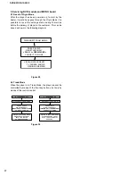
Page 18: ...OSE CONNECT TO MAINS VIRGIN MODE IS RESET TV SCREEN SHOWS VIRGIN MODE MENU Figure 29 5 2 Trade Mode When the player is in Trade Mode the player cannot be controlled by means of the front key buttons but only by means of the remote control DISCONNECT FROM MAINS IF TRADE MODE OFF PRESS 2 KEYS SIMULTANEOUSLY PREVIOUS OPEN CLOSE PREVIOUS OPEN CLOSE CONNECT TO MAINS DISCONNECT FROM MAINS IF TRADE MODE ...

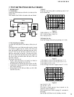
Page 19: ...filament voltage which is required for an AC FTD Generating the grid and segment scanning for the FTD Generating a scanning grid for the keys separated from display scanning Having inputs for RC RC5 and RC6 and P50 P50 controller is built in 1 3 Reset Check next reset timing with an oscilloscope at pin 10 of the microprocessor PM3392A ch1 ch2 CH1 2 00 V CH2 2 V BWL MTB 100ms 1 04dv ch2 1 2 T T1 Fi...

Page 20: ...ut ports via the I2C bus Send next command via the I2C bus Address 0x70 Command byte 0x24 Data byte xxxxabcd Where a Karaoke reset b Karaoke data c Karaoke clock d Karaoke strobe 1 8 P50 interface P50 is a bi directional serial interface which is used for communication between video equipment For European sets this communication goes via pin 10 of the scart bus In other regions it can be a cinch b...

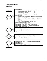
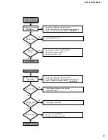
Page 21: ... connector 1115 4 40V 5 Check output voltage at anode of Diode 6102 10V 5 Check stabilizer 7112 output VKK 34V 7 Check 5Vstb voltage at connector 1115 3 5V 5 Check safety resistor R3117 Check 12V at connector 1115 1 12V 10 Check filament voltage AC voltage is created via uP output pin 19 generating a 42kHz duty cycle 45 55 square signal Check frequency 42kHz 10 Check buffered square output at emit...

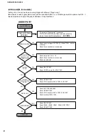
Page 22: ...no board Check mono board Check supply voltages 3V3 7400 8Vaud 7304 8Vstby 12Vstby Check flex connection to mono board NO YES PCM_OUT0 LRCLK SCLK PCM_CLK NO YES NO YES AUDIO CINCH OUTPUT TP 13 NO YES AUDIO TP 12 NO YES LEVEL OK YES N0 DISTORTION To put set in Player script press keys STOP OPEN CLOSE simultaneously and connect to mains Proceed until display shows APP SND 2 APP SND 2 A V board B G m...

Page 23: ...CLOSE simultaneously and connect to mains Proceed until display shows DIGITAL OUT OK Diagnostic Software NO DIGITAL OUTPUT DIG_OUT TP11 Check digital trafo L5400 Check flex connection to mono board Check mono board NO YES DIGITAL OUT TP18 NO YES To put set in Player script press keys STOP OPEN CLOSE simultaneously and connect to mains Proceed until display shows OPTICAL OUT Check 5V supply R3803 C...

Page 24: ...to mono board Check mono board Check supply voltages 8Vstby 8Vstby 12Vstby 6V 5V Check voltage regulator 7304 Check safety resistors 3615 3620 3802 3803 Check flex connection to mono board NO YES VIDEO TP1 6 NO NO YES YES NO YES VIDEO Y C OUT TP20 21 VIDEO CVBS CINCH TP19 To put set in Player script press keys STOP OPEN CLOSE simultaneously and connect to mains Proceed until display shows APP PIC ...

Page 25: ...ructions NO YES NO YES PICTURE AUX VCR IN ON TV To put set in Player script press keys STOP OPEN CLOSE simultaneously and connect to mains Proceed until display shows Diagnostic Software press NEXT Display shows Pressing PREVIOUS will return to Check 0 6 12 on connector 1300 8 0V Check flex connection to mono board Check SELECT 6V SELECT HIGH 12V Check transistors 7935 7943 Check switches 7900 790...

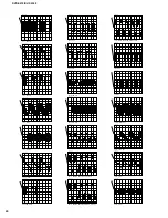
Page 26: ... PM3392A ch1 CH1 2 V MTB 100ns ch1 1 TP 11 DIG_OUT PM3392A ch1 CH1 1 V MTB 500us ch1 1 TP 12 ANALOG OUTPUT DAC PM3392A ch1 CH1 1 V MTB 500us ch1 1 TP 13 ANALOG OUTPUT AUDIO CINCH PM3392A ch1 CH1 1 V MTB 500us ch1 1 TP 14 ANALOG OUTPUT AUDIO HP_R HP_L PM3392A ch1 CH1 1 V MTB 500us ch1 1 TP 15 AUDIO SCART SWITCH OUTPUT PM3392A ch1 CH1 2 V MTB50 0ms ch1 1 PM3392A ch1 CH1 2 V MTB50 0ms ch1 1 PM3392A c...

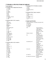
Page 27: ... I2C clock 2 GND 3 I2C data 4 Standby control line 5 P50 1 5 Connector 1602 Service connector 1 TXD 2 Service activation 3 RXD 4 Reserved for RTS 5 5 GND 6 Reserved for CTS 7 5V 2 Signal specifications This the specification of all signals as described under Connections H 5V 0 5V h 3 3V 0 3V L 0V 0 5V l 0V 0 3V Stby If the set supports a standby function all supply voltages marked with stby have t...

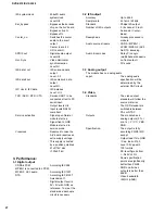
Page 28: ...o LPCM MPEG2 AC3 audio According IEC1937 DTS According IEC61937 Amendment 1 Digital output level is 0V 5V with GND as reference To meet the standards a decouple circuit is necesary 3 2 I2S output Accuracy Up to 24bit Sample rate 44 1kHz 48kHz Standard Philips I2S output Number of I2S outputs 3 6 channel Front Surround Center Bass Deemphasis Already processed in module Audio source streams CDDA MPE...

Page 29: ...for DAC PCM_OUT0 Audio serial output data R Buffered Video input Red from DVD monoboard RCIN_TV Red or Chroma input from TV scart RCOUT_TV Red or Chroma output to TV scart RIN_AUX Audio input right from AUX scart RIN_TV Audio input right from TV scart ROUT_AUX Audio output right to AUX scart ROUT_TV Audio output right to TV scart SCL I2C bus clock SCLK Audio serial bit clock SDA I2C bus data SELEC...

Page 30: ...y Serial I Face Push Pull 3 Beam Tracking Var Gain Balanced HF Servo Signals OPU Interface Control Interface DVD CD D1 D6 MUX FTC Land V I references R ext Header Offset Data header Mute compensations MUX FTC comp IC DESCRIPTIONS TZA1033 DVDALAS2plus Advanced Analog DVD Signal Processor and Laser Supply ...

Page 31: ...XT VDDA2 VSSA2 DVD LO RFN RFP RF REF VDDL CD MI TZA1023 TZA1033 DVDALAS2plus Advanced Analog DVD Signal Processor and Laser Supply Pin description Name Pin Description CD A 1 CD pick up input A CD B 2 CD pick up input B CD C 3 CD pick up input C CD D 4 CD pick up input D CD REF 5 CD pick up reference voltage CD E 6 CD pick up input E CD F 7 CD pick up input F DVD A 12 DVD pick up input A DVD B 13 ...

Page 32: ...MI 62 CD laser monitor input DVD MI 10 DVD laser monitor input CD LO 61 CD laser output DVD LO 64 DVD laser output COP 27 Positive input FTC comparator COM 28 Inverting input FTC comparator COO 29 FTC comparator output SIDA 23 Serial host interface data input SICL 24 Serial host interface clock input SILD 25 Serial host interface load VDDA1 8 Analog Supply voltage 1 RF input VDDA2 59 Analog Supply...

Page 33: ...AIN DRIVER MT1 29 MT2 30 NC1 NC2 NC3 NC4 NC5 PS 23 REV 24 RNF 28 VCC 25 VH 19 VM1 26 VM2 27 A1 A2 A3 CNF 20 EC 22 21 ECR FG1 18 FG2 17 FG3 16 GND 8 H1 H1 H2 H2 H3 H3 3 5 7 1 2 9 10 4 6 11 12 15 13 14 BA6856FP 3 Phase motor driver for DVD players ...

Page 34: ...input Amp1 negative input 11 H2 Hall input Amp2 positive input 12 H2 Hall input Amp2 negative input 13 H3 Hall input Amp3 positive input 14 H3 Hall input Amp3 negative input 15 N C Not connected 16 FG3 FG3 signal output terminal 17 FG2 FG2 signal output terminal 18 FG1 FG1 signal output terminal 19 VH Hall Bias 20 CNF Capacitor connection pin for phase compensation 21 ECR Torque control standard v...

Page 35: ...1 Iref REFLo REFHi VREF HFIN VSSA2 AGCOUT VDDA2 VDDD1 VSSD1 OTD MOTO1 n c MOTO2 T3 n c T1 T2 VDDD2 VSSD2 TEST1 TEST2 POR MUXSWICH n c RAMAD6 RAMAD5 RAMAD4 RAMAD3 RAMAD2 V DDA1 V SSD9 V DDD9 MEAS1 CFLG CROUT CRIN V SSD8 V DDD8 RAMAD14 RAMAD13 RAMAD12 RAMAD11 RAMAD10 n c RAMAD9 RAMAD8 RAMAD7 V SSD7 V DDD7 V DDD3 V SSD3 da7 da6 da5 n c da4 n c da3 da2 da1 n c da0 V DDD4 V SSD4 WRi RDi ALE CSi STOPCLO...

Page 36: ...lier input n c 25 not connected reserved CL1 26 O divided clock output BCAIN 27 I BCA input SDA 28 I O sub CPU I 2 C bus serial data input output SCL 29 I sub CPU I 2 C bus serial clock input INT 30 O sub CPU interrupt output open drain VDDD3 31 supply digital supply voltage 3 VSSD3 32 supply digital ground 3 da7 33 I O sub CPU data bus bit 7 input output parallel da6 34 I O sub CPU data bus bit 6...

Page 37: ... I O RAM data bus bit 0 input output VDDD6 72 supply digital supply voltage 6 VSSD6 73 supply digital ground 6 RAMAD0 74 O RAM address bit 0 output RAMAD1 75 O RAM address bit 1 output RAMAD2 76 O RAM address bit 2 output RAMAD3 77 O RAM address bit 3 output RAMAD4 78 O RAM address bit 4 output RAMAD5 79 O RAM address bit 5 output RAMAD6 80 O RAM address bit 6 output VDDD7 81 supply digital supply...

Page 38: ... Voltage Generator PGM Voltage Generator Timer VCC Detector State Control Command Register VCC VSS WE BYTE CE OE STB STB DQ0 DQ15 A 1 Sector Switches RY BY RESET Data Latch Y Gating Cell Matrix Address Latch A0 A19 Am29LV160B 16 MB 2 M x 8 bit 1 M x 16 bit CMOS 3 0 Volt only Sector Erase Flash Memory ...

Page 39: ...CONTROLLER 2 048 REFRESH COUNTER CAS 256 256 x16 8 COLUMN ADDRESS BUFFER BURST COUNTER ROW ADDRESS MUX CLK CS WE CKE 256 x16 BANK1 MEMORY ARRAY 2 048 x 256 x 16 SENSE AMPLIFIERS I O GATING DQM MASK LOGIC CONTROL LOGIC COLUMN DECODER COLUMN ADDRESS LATCH 8 MODE REGISTER ROW ADDRESS LATCH 11 ROW DECODER 11 COMMAND DECODE DQ0 DQ15 A0 A10 BA 16 8 DQML DQMH 256 2 048 BANK0 MEMORY ARRAY 2 048 x 256 x 16...

Page 40: ... G_OUT R_OUT I_REF_DAC_RGB V_REF_DAC_RGB V DDA V SSA Y_OUT C_OUT CV_OUT V_REF_DAC_YCC I_REF_DAC_YCC V DD GND AD 4 AD 5 AD 6 AD 7 AD 8 AD 9 V DD MEMCLKOUT GND AD 0 AD 1 AD 2 AD 3 AD 11 AD 10 SDCS 0 SDCS 1 V DD GND SDRAS SDCAS SDWE DQML DQ 0 DQ 1 DQ 2 V DD GND DQ 3 DQ 4 DQ 5 DQ 6 DQ 7 V DD GND MEMCLKIN DQMU DQ 8 DQ 9 DQ 10 DQ 11 VDD GND DQ 12 DQ 13 DQ 14 DQ 15 AUXCLK OSD_ACTIVE PIXCLK_27MHz VDD GND ...

Page 41: ...RCLK SCLK FFC PCM_CLK MIC GND 1 2 3 1 2 3 4 5 6 7 8 9 10 11 12 13 14 15 16 GND H_SYNC GND MONO BOARD 1 2 3 4 5 6 6VSTBY 8 CVBS GND 0 6 12 8V 13 14 15 16 17 18 19 20 21 22 P50 B G GND R CVBS GND 0 6 12 8V 1 2 3 4 5 ADJA_OUT ADJA_IN GND ADJB_IN 8 1 16 1 4 5 1 5 1 16 1 22 1 12 1501 1604 1603 1600 SCL GND SCA STBCONTROL P50 GND C GND Y P50 B G 7 R 280MM GND 8V 8 5VD 5WD KILL GND PCM_OUT0 LRCLK SCLK GN...

Page 42: ...I2C Y C Y UDA1328T 3 KILL 8Vstab 3V3stab 12Vstby Video IC s and audio buffers DAC L R ONLY DVD751 2x DAC DISPLAY BOARD DIG_OUT PCM MICRO 5Vstab 8Vstby Switches 8V 5V 8V OPTICAL OUTPUT DIGITAL OUTPUT RC 7104 1113 7400 7405 DVD732 ONLY 7403 7008 7002 CVBS1 CVBS RGB Y C CVBS2 7020 7023 12V stby 5V stby 5V stby 40V 5V 3V3 CB CR TDA 4780 KOK TC9409 5V 43 42 BLOCK DIAGRAM U C A R T ...

Page 43: ... Y C CVBS YC not on SCART CVBS CVBS 0 6 12V RGB UDA1328T 3 Kill 8Vstab 3V3stab 12Vstby Video IC s and audio buffers DAC RGB CVBS RGB CVBS CVBS AUDIO AUDIO AUDIO L R DAC SCART SCART DISPLAY BOARD RGB CVBS L R I2C DIG_OUT PCM 5Vstab 8Vstby Switches OPTICAL OUTPUT DIGITAL OUTPUT RC 7104 1113 TEA6420 AUDIO SCART SWITCHING 7917 7401 7403 7900 7905 12V stby 5V stby 5V stby 40V 5V 3V3 45 44 BLOCK DIAGRAM...

Page 44: ...A B C D E F G H I J 1 2 3 4 5 7 DVD S510 DV S5350 6 47 46 PRINTED CIRCUIT BOARD MONO Bottom view ...

Page 45: ...A B C D E F G H I J 1 2 3 4 5 6 7 DVD S510 DV S5350 49 48 PRINTED CIRCUIT BOARD MONO Detailed bottom view 1 2 ...

Page 46: ...A B C D E F G H I J 1 2 3 4 5 7 DVD S510 DV S5350 6 51 50 PRINTED CIRCUIT BOARD MONO Detailed bottom view 2 2 ...

Page 47: ...A B C D E F G H I J 1 2 3 4 5 6 7 DVD S510 DV S5350 53 52 PRINTED CIRCUIT BOARD MONO Top view ...

Page 48: ...A B C D E F G H I J 1 2 3 4 5 7 DVD S510 DV S5350 6 55 54 PRINTED CIRCUIT BOARD MONO Detailed top view 1 2 ...

Page 49: ...A B C D E F G H I J 1 2 3 4 5 6 7 DVD S510 DV S5350 57 56 PRINTED CIRCUIT BOARD MONO Detailed top view 2 2 ...

Page 50: ...A B C D E F G H I J 1 2 3 4 5 7 DVD S510 DV S5350 6 59 58 PRINTED CIRCUIT BOARD A V U C A R T ...

Page 51: ...A B C D E F G H I J 1 2 3 4 5 6 7 DVD S510 DV S5350 _Z _A 61 60 PRINTED CIRCUIT BOARD A V B G ...

Page 52: ...A B C D E F G H I J 1 2 3 4 5 7 DVD S510 DV S5350 6 63 62 PRINTED CIRCUIT BOARD DISPLAY ...

Page 53: ...A B C D E F G H I J 1 2 3 4 5 6 7 DVD S510 DV S5350 65 64 PRINTED CIRCUIT BOARD POWER B G ...

Page 54: ...D2 T138 D2 1 2 3 4 GREEN SYMBOL CQW10 STANDBY D1 Standby PCB To Con 1117 of Display PCB C1 Volume Adjust PCB To Con 1201 of Headphone PCB Only for KOK version only 1 2 1 2 A B C D A B C D 1111 D1 SKQNAB 1111 1205 EH S T134 LTL 1CHPE 6204 3150 100R T137 T138 T136 T135 T123 T121 T124 EH B 1204 1 2 3 4 5 T122 T125 1 3 3239 A 10K 2 1 3 3237 3238 A 10K 2 1K5 3240 1K5 67 66 PRINTED CIRCUIT BOARD VOLUME ...

Page 55: ... 4 4 BA5938FM F113 12K 3149 F102 10K 3146 5V 1K5 3103 3V3S F148 8 4 F175 BC847B 7114 LM833D 7104 B 5 6 7 12K 1 5V F141 F109 3142 100R F130 F125 3156 47u 3185 1R 2103 1100 1 1 F105 F184 F121 1 3 2 F191 1R 3178 7101 BFS20 3101 47R 3193 3194 100R 3158 220p 3135 2R2 5V 2144 22p 2141 5V 100n 2138 2R2 12Vstby 1105 F104 3107 2137 100n 7113 BC847B F014 F036 BC847B 7112 F037 F158 6 7 8 9 F178 F133 13 14 15...

Page 56: ...20 REFCOS 9 REFSIN 8 80 RP 98 RSTI 33 RXD1 14 INT3 ALEh 114 IREFT 97 LDON 94 LLP 74 MON_A 73 MON_D NC1 2 NC2 3 36 NC3 37 NC4 NC5 67 NC6 100 NC7 101 NC8 OPC_INT 88 79 OTD FOK 115 FTCH 116 FTCL 23 H0 A16 H1 A17 24 25 H2 CSDN 26 H3 CSBN 27 H4 H5 28 29 H6 30 H7 90 I2CSCL 91 I2CSDA INT0_PWD 35 38 INT1 13 INT2 ALPHAO 77 ATIPin 123 CALF 76 CLKOUT 86 CLO COSPHI 126 106 D1 MIRN D2 TLN 107 108 D3 REN D4 FEN...

Page 57: ...00 F357 3320 F302 2301 100n 4K7 F356 F314 5VB F309 F352 F340 F344 F318 F345 5VB 1300 CSTCC 100n 2309 F310 3330 22K 1R 5V F347 F333 3316 VM1 27 VM2 5V F308 H3 14 H3 29 MT1 30 MT2 1 NC1 2 NC2 4 NC3 NC4 6 15 NC5 23 PS 24 REV 28 RNF 25 VCC 19 VH 26 7304 7 A1 5 A2 3 A3 20 CNF 22 EC ECR 21 18 FG1 17 FG2 16 FG3 8 GND 9 H1 10 H1 11 H2 12 H2 13 5VB 5VB BA6856FB 6K8 3325 4R7 3300 2311 F323 3340 100n 5V F313...

Page 58: ...6 5 4 7404 MT48LC1M16A1TG A0 21 A1 22 20 A10 A2 23 A3 24 A4 27 7403 74HCT1G04 2 3 1 NC 3407 22R 2411 100n VDD_MEM2 5V_DS 5402 100MHZ 100n 2404 100n 2400 7400 A 74HCT00D 1 2 7 14 3 5V_DS VDD_MEM2 VDD_MEM2 10K 3404 F424 5V_DS 100n 2401 100n 2414 5V_DS 3405 10K 2406 100n 100MHZ 5400 VDD_MEM 5Vstby 2416 100n 5V_DS 100n 2408 3421 10K 3420 10K 3V3 3418 100n 2410 2415 100n VDD_MEM2 100R 3401 VDD_MEM2 3V3...

Page 59: ...STn 29 R_OUT 57 133 R W_ DMAACK SCLK 43 SDCASn 89 SDCS0n 84 SDCS1n 85 SDRASn 88 SDWEn 90 SPDIF_OUT 47 TCK 188 202 PIO 3 2 203 PIO 3 3 204 PIO 3 4 205 PIO 3 5 206 PIO 3 6 207 2 PIO 3 7 PIO 4 0 191 PIO 4 1 192 PIO 4 2 193 PIO 4 3 194 PIO 4 4 195 PIO 4 5 196 PIO 4 6 197 PIO 4 7 14 PIXCLK_27MHz 118 17 PIO 0 5 20 PIO 0 7 22 PIO 1 0 9 PIO 1 2 10 PIO 1 3 198 199 PIO 1 4 PIO 1 5 11 PIO 1 6 12 PIO 1 7 13 P...

Page 60: ...5610 22K 3618 LD1117 7605 1 GND 3 IN 2 OUT F613 7613 3622 100R 5Vstby BC847B 7600 C 74HCT14D 5 6 14 7 3 5V 6Vstby 1603 3 3683 3V3 330R 3667 1 1603 4 4 F610 PH S 1602 1 430R F664 3V3 3661 1603 5 5 2642 22p F617 2604 100u 74HCT14D 7600 E 11 10 14 7 3605 F627 3V3 5V 5V 7610 BC847B F674 10u 2608 F659 22p 2646 BC857B 7608 5V 3636 6K8 22p 2641 Vvid 47R 3672 2626 47p 6Vstby 2625 47p 1603 14 14 1K 3626 F6...

Page 61: ...3 1V5 0V8 0V3 4011 5V 4010 100u 2016 3052 2K2 7411 BC847B 220p 1K 3047 10R 3049 BC847B 7415 5V 8 4 11 AD8073 7001 B 10 9 820R 3007 2009 TP3 TP6 TP4 6004 BZX284 C15 AD8073 7001 A 6K8 3030 3020 TP15 TP16 4K7 3067 2015 220p 75R 3056 2007 470n 7408 5VVID 3039 3059 5K6 7409 BC817 25 5V 75R 3009 3057 5VA 680R 3035 1006 C 8K2 3017 4008 5V TCS79 1003 1K2 BC847B 0 6 12 9102 5006 3014 5VVID 3011 4K7 3043 10...

Page 62: ...2210 47u 3222 TP7 1n 2213 ST_R ST_L DGND 3219 680R TP9 TP8 5K6 3216 2200 TP10 TP12 TP13 5VA 1 2 3 920927152B 5008 7450 2217 470n GP1F32T 7028 3 1 2 5VA 3215 2K7 2226 47p BC817 25 7456 8V 1011 YKC21 3416 7452 BC817 25 7453 2229 100p TP11 3V3_A OUT 100n 2224 3209 2K7 5VA 2207 47u 5VA 7 8 4 GND IN 7010 LF33CV 3225 100R 0 6 12 100u 2205 680R 3203 100u 10K 3208 5K6 100n 2206 3211 10K 4 6 7 8 3V3_D 3227...

Page 63: ... 22n 2528 2527 22n 22n 2536 47K 3770 47u 12Vstby 2453 F273 F503 F274 F269 F270 3V3 8Vstby 4R7 3615 12Vstby 3618 1K 10K 3619 10K 3617 2534 22n 7331 BC547B 6V 220n 2384 E 6 S 10 Vdd 16 Vee 7 Vss 8 Y0 2 Y1 1 Z 15 F281 HEF4053BT 7905 B 22n 2530 BC847B 7935 F130 1300 2 2 6404 BZX284 C5V1 270R 3762 E 6 S 9 Vdd 16 Vee 7 Vss 8 Y0 5 Y1 3 Z 4 U185 HEF4053BT 7905 C 14 U183 HEF4053BT 7904 A E 6 S 11 Vdd 16 Ve...

Page 64: ...447 2K7 100R 3517 6 5 STEREO_R STEREO_L YKC21 3930 1402 B 4 3 YKC21 3930 1402 C 5V 12 F177 BC847B 7329 F141 52030 1300 12 F139 F416 F437 F424 F417 F413 F421 2360 50 2373 4u7 47p 100R 3322 47p 2361 1K 3339 3321 100R F403 2372 50 4u7 3767 22K 3V3 22K 3766 U191 7948 BC857B U189 U190 F505 8Vstby 4R7 3803 F448 F455 2464 5V 100p 2461 100p 100p 2455 100p 2459 7405 BC817 40 BC817 40 7407 2496 22n 3635 220...

Page 65: ...100K 3641 100K 3643 100K 3639 7928 BC847B 100K 3646 BC857B 7938 3638 100K 3640 100K 3642 100K 3721 150R 2501 220p 2523 8Vstby 8Vstby 220p 100R 330R 3650 3682 100R 3683 U136 1K 3699 75R 3674 8Vstby 7927 BC847B 8Vstby 330R 3732 2507 2u2 U223 U220 U221 8Vstby U219 U216 U214 U215 U212 U213 U210 U211 8Vstby U209 3673 75R BC847B 7925 3698 1K 3704 6K8 8Vstby 7919 BC847B U159 U160 U161 U134 U157 U158 U154...

Page 66: ...BS YC B C F G I208 75R 3049 470n 2032 5V 5V I245 3041 8K2 3036 2K2 5V 22K 7006 BC847B 8Vstby 3038 8Vstby I246 I251 U130 F101 I219 I221 1402 A 2 1 YKC21 3930 8Vstby 8Vstby I196 3301 100R 330R 3300 7301 BC847B BC857B 7300 1K 3347 75R 3345 7310 BC847B 2505 220p 330R 3743 I241 I211 3742 330R I242 3760 100K 8Vstby 220R 3050 I210 I247 I215 8Vstby 8Vstby I214 330R 3043 100R 3045 I189 8Vstby 1K 3063 100R ...

Page 67: ... 28 29 30 31 32 1113 1 10 11 12 13 14 15 16 17 18 19 2 20 F204 14 MT 26GNK F165 F166 2107 39n F217 F168 3134 330R 27K 3101 F120 3118 10K F129 F161 F216 F119 F181 2211 BAS216 6100 3107 0R 100p F121 10K 3140 2128 1n 22u 2130 3100 22K 2119 22p 3145 10K F153 VKK 2114 22p 3109 SKQNAB 1101 4K7 3126 10R 10R 3128 F164 3138 470R 3105 0R 2131 1n 5Vstb 2202 1n 5Vstb 22p 2121 F202 10R 3133 F212 1110 VKK 6101 ...

Page 68: ... Standby 7237 TL431CZ 2260 22u 6250 BYD33J 100n 2143 5Vstby CQY80NG 7131 5V 6141 UDZ 18B 6Vstby 15K 3153 1 2 6260 3202 1K8 2157 470p 0206 EH B 2122 33n 3253 2234 33n 6Va BZX79 C15 6123 270R 3204 6122 BZX79 C15 2129 22u 2253 7259 GND IN OUT 1 2 3 4 0208 EH B BYD33J 6261 1n 2241 47R 3139 1N4148 6140 T2 5A H 250V VALUE 1120 2239 220u 220R 3140 BYW29EX 6240 5222 40V 5230 10u Off_2 5V 5V 15K 3235 12V 3...

Page 69: ...FILTER EMI GND MTL GROUND PLATE GND TERM GROUND TERMINAL HOLDER FUS FUSE HOLDER IC PRTCT IC PROTECTOR JUMPER CN JUMPER CONNECTOR JUMPER TST JUMPER TEST POINT L DTCT LIGHT DETECTING MODULE L EMIT LIGHT EMITTING MODULE LED DSPLY LED DISPLAY LED INFRD LED INFRARED MODUL RF MODULATOR RF PHOT CPL PHOTO COUPLER PHOT INTR PHOTO INTERRUPTER PHOT RFLCT PHOTO REFLECTOR PIN TEST PIN TEST POINT PLST RIVET PLA...

Page 70: ...S135100 C CE CHP 0 1uF 16V 4822 126 14305 2303 UF017470 C EL CHP 47uF 6 3V 4822 124 80349 2306 UF037100 C EL CHP 10uF 16V 4822 124 23002 2309 US135100 C CE CHP 0 1uF 16V 4822 126 14305 2310 US135100 C CE CHP 0 1uF 16V 4822 126 14305 2314 US135100 C CE CHP 0 1uF 16V 4822 126 14305 2315 US135100 C CE CHP 0 1uF 16V 4822 126 14305 2318 US062120 C CE CHP 120PF 50V 5322 122 33861 2319 US061270 C CE CHP ...

Page 71: ...0KΩ 1 10W 4822 117 13632 3608 HX609660 R MTL CHP 100KΩ 1 10W 4822 117 13632 3609 HX609660 R MTL CHP 100KΩ 1 10W 4822 117 13632 3693 HX609650 R MTL CHP 47KΩ 1 10W 4822 117 12925 5200 AAX22070 COIL BLM31P500SPT 4822 157 11717 5300 AAX22070 COIL BLM31P500SPT 4822 157 11717 5301 AAX22070 COIL BLM31P500SPT 4822 157 11717 5402 AAX22050 COIL BLM11P600SPT 4822 157 11499 5403 AAX22050 COIL BLM11P600SPT 482...

Page 72: ...0W 4822 117 13611 3050 HX609900 R MTL CHP 1 5KΩ 1 16W 5322 117 13034 3053 HX609640 R MTL CHP 1KΩ 1 10W 4822 117 13611 3054 HX609640 R MTL CHP 1KΩ 1 10W 4822 117 13611 3055 HX609640 R MTL CHP 1KΩ 1 10W 4822 117 13611 3057 HX610030 R MTL CHP 1 2KΩ 1 10W 5322 117 13036 3060 HX609640 R MTL CHP 1KΩ 1 10W 4822 117 13611 3061 HX609960 R MTL CHP 6 8KΩ 1 16W 5322 117 13053 3208 HX610400 R MTL CHP 8 2KΩ 1 1...

Page 73: ...0 C CE M CHP 0 22uF 25V 2527 UB044220 C CE M CHP 0 022uF 50V 2528 UB044220 C CE M CHP 0 022uF 50V 2529 UB044220 C CE M CHP 0 022uF 50V 2530 UB044220 C CE M CHP 0 022uF 50V 2531 UB044220 C CE M CHP 0 022uF 50V 2532 UB044220 C CE M CHP 0 022uF 50V 2533 UB044220 C CE M CHP 0 022uF 50V 2534 UB044220 C CE M CHP 0 022uF 50V 2535 UB044220 C CE M CHP 0 022uF 50V 2536 UB044220 C CE M CHP 0 022uF 50V 2537 U...

Page 74: ... TR CHP BC847B 4822 130 60511 7931 AAX22740 TR CHP BC847B 4822 130 60511 7933 AAX22740 TR CHP BC847B 4822 130 60511 7934 AAX22740 TR CHP BC847B 4822 130 60511 7935 AAX22740 TR CHP BC847B 4822 130 60511 7936 AAX22730 TR CHP BC856B 4822 130 60373 7937 AAX22730 TR CHP BC856B 4822 130 60373 7938 AAX22730 TR CHP BC856B 4822 130 60373 7939 AAX22730 TR CHP BC856B 4822 130 60373 7941 AAX22730 TR CHP BC856...

Page 75: ...ANF 4822 146 10402 5210 AAX22080 COIL 6 8uH 7 7x9 5 4822 157 11722 5223 AAX22090 COIL 2 2uH 4822 157 50963 s 5231 AAX22080 COIL 6 8uH 7 7x9 5 4822 157 11722 5240 AAX22100 COIL 1uH 4x9 8mm 4822 157 51195 5260 AAX22060 COIL 10uH 2 3x3 4 4822 157 11517 6110 AAX22610 DIODE 1N4004G 5322 130 34574 6111 AAX22610 DIODE 1N4004G 5322 130 34574 6120 AAX22600 DIODE SINB80 4822 130 83707 6122 AAX22570 DIODE BZ...

Page 76: ... 35 57 55 201 202 203 204 59 3 x 10 36 x6 3 x 10 36 x9 3 x 10 36 3 x 10 36 53 40 7 Standby board 5 1 2 4 2 7 mm for screws with 33 35 and 36 1 7 mm for removing MONO board 18 2 from DVD Mechanism 18 1 105 104 EXPLODED VIEW When disassembling use the special screw driver with tip shape in figure Note The screw to fix the MONO board 18 2 to the DVD mechanism 18 1 is not available ...

Page 77: ... 52502 UC 24 AAX23160 REAR PANEL S510 3139 247 52513 GB 24 AAX23170 REAR PANEL S510 3139 247 52522 R 24 AAX23180 REAR PANEL S510 3139 247 52532 A 24 AAX23200 REAR PANEL S510 3139 247 53851 T 24 AAX23190 REAR PANEL S5350 3139 247 52742 U 32 AAX22820 TOP COVER BL 3139 247 50341 32 AAX22830 TOP COVER GD 3139 247 52481 32 AAX22840 TOP COVER TI 3139 247 52491 33 AAX23640 PAN HEAD TORX S TITE SCREW 3x6 ...

Page 78: ...OWER CORD ASS Y 1 8m 1pc 3111 170 21831 G s 201 AAX23380 POWER CORD ASS Y 1 8m 1pc 3103 140 26741 B 202 AAX23450 AUDIO VIDEO CORD YE RD WH 1 5m 1pc 2422 076 00304 UCART 203 AAX21980 AUDIO CORD RD WH 1 5m 1pc 3103 308 92611 GB 204 AAX22970 VIDEO CORD YE 1 5m 1pc 3104 108 45432 GB Ref No PART NO Description Remarks Markets AAX21470 DVD MECHANISM BASIC ENGINE 9305 023 61102 4 AAX23070 BELT DRIVING 48...

Reviews: