background image

SERVICE MANUAL

1 0 1 0 5 0

SERVICE MANUAL

P.O.Box 1, Hamamatsu, Japan

SERVICE  MANUAL

IMPORTANT NOTICE

This manual has been provided for the use of authorized YAMAHA Retailers and their service personnel.
It has been assumed that basic service procedures inherent to the industry, and more specifically YAMAHA Products, are already
known and understood by the users, and have therefore not been restated.

WARNING:

Failure to follow appropriate service and safety procedures when servicing this product may result in personal
injury, destruction of expensive components, and failure of the product to perform as specified.  For these reasons,
we advise all YAMAHA product owners that any service required should be performed by an authorized
YAMAHA Retailer or the appointed service representative.

IMPORTANT:

The presentation or sale of this manual to any individual or firm does not constitute authorization, certification or
recognition of any applicable technical capabilities, or establish a principle-agent relationship of any form.

The data provided is believed to be accurate and applicable to the unit(s) indicated on the cover.  The research, engineering, and
service departments of YAMAHA are continually striving to improve YAMAHA products.  Modifications are, therefore, inevitable
and specifications are subject to change without notice or obligation to retrofit.  Should any discrepancy appear to exist, please
contact the distributor's Service Division.

WARNING:

Static discharges can destroy expensive components.  Discharge any static electricity your body may have
accumulated by grounding yourself to the ground buss in the unit (heavy gauge black wires connect to this buss).

IMPORTANT:

Turn the unit OFF during disassembly and part replacement.  Recheck all work before you apply power to the unit.

CONTENTS

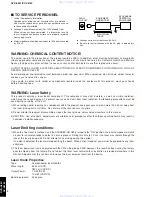
TO SERVICE PERSONNEL ...................................... 2–3
PREVENTION OF ELECTROSTATIC DISCHARGE 
.... 4
LOCALE MANAGEMENT INFORMATION 
................... 4
FRONT PANELS 
............................................................ 5
REAR PANELS 
........................................................... 5-6
REMOTE CONTROL PANEL 
........................................ 6
SPECIFICATIONS ...................................................... 
6–7
INTERNAL VIEW 
........................................................... 8
REPAIR NOTES 
............................................................. 9
TRADE MODE ................................................................ 
9

 2007                                         All rights reserved.

This manual is copyrighted by YAMAHA and may not be copied or

redistributed either in print or electronically without permission.

DVD-S661/

DV-S6160

 '07.05

This service manual is for the DVD-S661/DV-S6160 (U, K, A, L, P models).
For the DVD-S661 (G model) service manual, please refer to the following service manual:

DVD-S661 (G model):  101047

For U, K, A, L, P models

DISASSEMBLY PROCEDURES ................................. 10
TEST MODE 
................................................................. 11
BLOCK DIAGRAM 
....................................................... 12
WIRING DIAGRAM 
...................................................... 13
PRINTED CIRCUIT BOARDS ................................ 
14–19
SCHEMATIC DIAGRAMS ...................................... 
20–26
REPLACEMENT PARTS LIST 
.............................. 28–29
REMOTE CONTROL .................................................... 
29
SCENE CONTROL ....................................................... 
30

DVD-S661/DV-S6160

DVD PLAYER

www. xiaoyu163. com

QQ 376315150

9

9

2

8

9

4

2

9

8

TEL 13942296513

9

9

2

8

9

4

2

9

8

0

5

1

5

1

3

6

7

3

Q

Q

TEL  13942296513  QQ  376315150  892498299 

TEL  13942296513  QQ  376315150  892498299 

http://www.xiaoyu163.com

http://www.xiaoyu163.com

Summary of Contents for DV-S6160

Page 1: ...out notice or obligation to retrofit Should any discrepancy appear to exist please contact the distributor s Service Division WARNING Static discharges can destroy expensive components Discharge any static electricity your body may have accumulated by grounding yourself to the ground buss in the unit heavy gauge black wires connect to this buss IMPORTANT Turn the unit OFF during disassembly and pa...

Page 2: ...re applicable components may also contain traces of chemicals found by the California Health and Welfare Agency and possibly other entities to cause cancer and or birth defects or other reproductive harm DO NOT PLACE SOLDER ELECTRICAL ELECTRONIC OR PLASTIC COMPONENTS IN YOUR MOUTH FOR ANY REASON WHATSOEVER Avoid prolonged unprotected contact between solder and your skin When soldering do not inhal...

Page 3: ...s possible to touch copper tracks and or components when servicing the player Service personnel have to take precautions to prevent touching this area or components in this area Note The screws on the DVD mechanism may never be touched removed or re adjusted Handle the DVD mechanism with care when the unit has to be exchanged The DVD mechanism is very sensitive for dropping or giving shocks www xi...

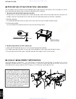
Page 4: ...res have been completed 1 Worktable grounding Put a grounded conductive material sheet or iron sheet on the area where the optical pickup is placed 2 Human body grounding Use an anti static wrist strap to discharge the static electricity from your body 1M ohms Conductive material sheet or steel sheet Anti static wrist strap 2 Handling Precautions for DVD mechanism 1 Handle the DVD mechanism gently...

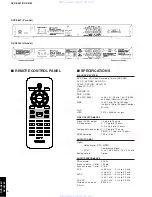
Page 5: ...model DV S6160 U model DVD S661 K model DVD S661 A model DVD S661 L model www xiaoyu163 com QQ376315150 9 9 2 8 9 4 2 9 8 TEL 13942296513 9 9 2 8 9 4 2 9 8 0 5 1 5 1 3 6 7 3 Q Q TEL 13942296513 QQ 376315150 892498299 TEL 13942296513 QQ 376315150 892498299 http www xiaoyu163 com http www xiaoyu163 com ...

Page 6: ...s PB PR 0 7 Vpp into 75 ohms HDMI upscaling 720 p 1080 i AUDIO FORMAT Digital Dolby Digital DTS MPEG Compressed digital PCM fs 44 1 48 96 kHz 16 20 24 bits Analog sound Stereo AUDIO PERFORMANCE DA converter 24 bits Signal to noise 1 kHz 105 dB Dynamic range 1 kHz 97 dB DVD fs 96 kHz 2 Hz to 44 kHz fs 48 kHz 2 Hz to 22 kHz SVCD fs 48 kHz 2 Hz to 22 kHz fs 44 1 kHz 2 Hz to 20 kHz CD VCD fs 44 1 kHz ...

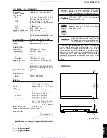
Page 7: ...0 60 Hz A L P models Power consumption Approx 14 W Standby power consumption Less than 1 W ACCESSORIES Remote control x 1 Battery AAA R03 UM 4 x 2 Audio video cable 1 5 m x 1 Specifications are subject to change without prior notice U U S A model K Korean model A Australian model L Singapore model P South America model DivX DivX Ultra Certified and associated logos are trademarks of DivX Inc and a...

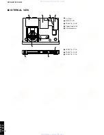
Page 8: ...ower Supply Unit 5 DVD Mechanism 6 FRONT 2 P C B 7 FRONT 1 P C B 8 FRONT 3 P C B 5 www xiaoyu163 com QQ376315150 9 9 2 8 9 4 2 9 8 TEL 13942296513 9 9 2 8 9 4 2 9 8 0 5 1 5 1 3 6 7 3 Q Q TEL 13942296513 QQ 376315150 892498299 TEL 13942296513 QQ 376315150 892498299 http www xiaoyu163 com http www xiaoyu163 com ...
Page 9: ...onds later the tray is closed automatically Fig 4 Fig 1 Fig 2 TRADE mode display Fig 3 Fig 4 Enter Cancel None of the components of the following unit can be supplied separately Each unit must be replaced as a whole in case of a failure REPAIR NOTES STANDBY ON key Tray FL Display OPEN CLOSE key DVD Mechanism MONO P C B FRONT P C B AV P C B Power Supply Unit Notes After activating TRADE mode it is ...

Page 10: ... Remove cable connection 1200 FRONT P C B Front Panel 101 Remove 4 cables connections 1105 1205 CN3 1301 Open tray Fig 2 Unlock tray lid and close tray Remove 2 screws 251 Front panel to frame Unlock front panel by releasing successively 4 snaps 2 on sides and 2 on bottom side Mounting Dismounting See REPLACEMENT PARTS LIST for item numbers 2 7 mm When disassembling use T10 TORX screwdriver as sho...

Page 11: ...nitial display Initial display All segments on Lighting of segments in lattice OFF OFF ON OFF ON OFF Canceling Test Mode Disconnect the power cable from the AC power outlet Press OPEN CLOSE key of the main unit Press STANDBY ON key of the main unit Press OPEN CLOSE key of the main unit Press PLAY key of the main unit Press PAUSE key of the main unit Press STOP key of the main unit Press PLAY PAUSE...

Page 12: ...42 27 14 38 10 12 KEY1 3 6121 6122 16 15 12 11 10 9 AUDIO OUT L R HDMI AV MONO FRONT Power Supply Unit AV DVD Mechanism See page 23 24 SCHEMATIC DIAGRAM See page 25 26 SCHEMATIC DIAGRAM See page 20 22 SCHEMATIC DIAGRAM See page 23 24 SCHEMATIC DIAGRAM SC SY 7300 7106 INT_IR EXT_IR D D SFH615 1 4 3 2 5V_STBY 187 179 181 38 39 189 191 182 183 185 12V 12V 5V DIGITAL OUT Y PB PR COMPONENT S VIDEO AC I...

Page 13: ...Vc F VCC GND PD B A 1101 24 15 14 13 12 11 10 9 8 7 6 23 5 4 3 2 1 22 21 20 19 26 27 28 29 3 30 4 5 6 7 8 9 TRIN LOAD LOAD GND C NC VR CD LD CD E VR DVD NC MD GND LD LD DVD HFM F T F D 18 19 2 20 21 22 23 24 25 1 26 S0 GND 30FE BT VK N 1201 B5B EH A 1 10 11 12 13 14 15 16 17 18 19 2 20 21 22 23 24 25 GND NC GND GND LRCLK BCLK MCLK Y_G CVBS GND B_Cb_Pb GND NC PCM_DATA0 GND RXD 4 3 2 1 PH 1104 1201 ...

Page 14: ...2xxx Capacitor 4xxx SMD jumper 6xxx Diode 9xxx Wire jumper DVD Mechanism Unit AV 1100 MONO DVD Mechanism Unit FRONT 3 1522 AV 1201 FRONT 1 1102 Top view HDMI w w w x i a o y u 1 6 3 c o m Q Q 3 7 6 3 1 5 1 5 0 9 9 2 8 9 4 2 9 8 T E L 1 3 9 4 2 2 9 6 5 1 3 9 9 2 8 9 4 2 9 8 0 5 1 5 1 3 6 7 3 Q Q TEL 13942296513 QQ 376315150 892498299 TEL 13942296513 QQ 376315150 892498299 http www xiaoyu163 com htt...

Page 15: ...FET 2xxx Capacitor 4xxx SMD jumper 6xxx Diode 9xxx Wire jumper MONO Bottom view w w w x i a o y u 1 6 3 c o m Q Q 3 7 6 3 1 5 1 5 0 9 9 2 8 9 4 2 9 8 T E L 1 3 9 4 2 2 9 6 5 1 3 9 9 2 8 9 4 2 9 8 0 5 1 5 1 3 6 7 3 Q Q TEL 13942296513 QQ 376315150 892498299 TEL 13942296513 QQ 376315150 892498299 http www xiaoyu163 com http www xiaoyu163 com ...
Page 16: ...ire jumper MONO 1201 MONO 1207 Power Supply Unit CN1 VIDEO S VIDEO AUDIO OUT L R COMPONENT Y PB PR DIGITAL OUT COAXIAL AV Top view w w w x i a o y u 1 6 3 c o m Q Q 3 7 6 3 1 5 1 5 0 9 9 2 8 9 4 2 9 8 T E L 1 3 9 4 2 2 9 6 5 1 3 9 9 2 8 9 4 2 9 8 0 5 1 5 1 3 6 7 3 Q Q TEL 13942296513 QQ 376315150 892498299 TEL 13942296513 QQ 376315150 892498299 http www xiaoyu163 com http www xiaoyu163 com ...

Page 17: ... FET 2xxx Capacitor 4xxx SMD jumper 6xxx Diode 9xxx Wire jumper AV Bottom view w w w x i a o y u 1 6 3 c o m Q Q 3 7 6 3 1 5 1 5 0 9 9 2 8 9 4 2 9 8 T E L 1 3 9 4 2 2 9 6 5 1 3 9 9 2 8 9 4 2 9 8 0 5 1 5 1 3 6 7 3 Q Q TEL 13942296513 QQ 376315150 892498299 TEL 13942296513 QQ 376315150 892498299 http www xiaoyu163 com http www xiaoyu163 com ...
Page 18: ...ONT 2 1200 OPEN CLOSE HDMI LED PLAY PAUSE STOP PROGRESSIVE LED FRONT 1 FRONT 1 FRONT 4 1301 Power Supply Unit CN3 MONO 1206 Bottom view Top view w w w x i a o y u 1 6 3 c o m Q Q 3 7 6 3 1 5 1 5 0 9 9 2 8 9 4 2 9 8 T E L 1 3 9 4 2 2 9 6 5 1 3 9 9 2 8 9 4 2 9 8 0 5 1 5 1 3 6 7 3 Q Q TEL 13942296513 QQ 376315150 892498299 TEL 13942296513 QQ 376315150 892498299 http www xiaoyu163 com http www xiaoyu1...
Page 19: ... a component indicates the component type 1xxx Connector 3xxx Resistor 5xxx Coil 7xxx IC Transistor FET 2xxx Capacitor 4xxx SMD jumper 6xxx Diode 9xxx Wire jumper w w w x i a o y u 1 6 3 c o m Q Q 3 7 6 3 1 5 1 5 0 9 9 2 8 9 4 2 9 8 T E L 1 3 9 4 2 2 9 6 5 1 3 9 9 2 8 9 4 2 9 8 0 5 1 5 1 3 6 7 3 Q Q TEL 13942296513 QQ 376315150 892498299 TEL 13942296513 QQ 376315150 892498299 http www xiaoyu163 co...
Page 20: ... 184 185 RD19 186 RD18 187 RD17 188 RD16 DACVDDC 189 175 DVSS_11 RD25 176 RD24 177 178 DQM3 DQM2 179 TNI 18 RD23 180 181 RD22 RD31 168 RD30 169 17 CDFOP 170 RD29 RD28 171 RD27 172 DVDD18_5 173 RD26 174 160 RA8 DVSS_9 161 162 RA7 DVSS_10 163 RA6 164 RA5 165 RA4 166 167 DVDD3_7 153 RVREF 154 RCLKB DVDD3_6 155 RCLK 156 157 CKE 158 RA11 159 RA9 16 CDFON RA10 146 RA0 147 148 DVSS_8 149 RA1 15 SD 150 RA...

Page 21: ... 46 52 16 100n 36 40 18 1 14 27 3 9 43 49 5 7 8 10 11 13 42 44 39 15 37 38 19 2 4 45 47 48 50 51 53 25 26 29 30 31 32 33 34 20 21 17 Φ DRAM 1M X 16 X 4 23 24 22 35 F205 7206 IS42S16400A F224 5203 1u8 6 5 8 4 7 EEPROM Φ 2Kx8 1 2 3 M24C16 RDW6 7212 2 3 1 5 4 74HC1G125GW 7201 F212 D 5V_STBY 4203 3270 150R F228 100n 2246 DV33 3240 150R 150R 3207 2206 47p F218 150R 3235 150R 3256 3258 100n F249 3251 15...

Page 22: ... 2 7 14 3 7303 1 74LVC08APW 1 47R 3310 3313 47R 1302 200mA BLM18P 5306 BSN20 7307 3 1 2 2314 3 2 6 7 8 100n Φ LTC4300A 2IMS8 7302 1 4 5 51 VSS1 3 78 VSS2 40 VSSD 19 WRF 77 XDN 64 VID 9 VIE 12 VIF 80 VIG 13 VIH 1 VREF 79 VSS1 1 46 VSS1 2 VDD1 1 8 VDD1 2 11 VDD1 3 55 VDD2 36 VDDL 75 VIA 10 VIB 4 VIC 3 SICL 35 SIDA 34 SILD 32 SROUT 68 TEST 71 TIMOUT 18 TS1 31 TS2 30 RREF 52 RRF 76 R W 14 S1 59 S2 58 ...

Page 23: ...01 4104 T104 T124 2136 470u 6 3V 7 6 7108 1 BC847BS MSP 801V1 02 01 B NI FE LF 1102 B 3124 10K 3130 10K 4100 3165 10K 10K 3163 T117 3132 10K T103 1K0 3131 T111 T128 6 7 8 9 24 25 26 27 28 29 3 30 4 5 14 15 16 17 18 19 2 20 21 22 23 1100 1 10 11 12 13 220p 2116 10K 6101 PDZ 15B T116 3133 2133 100n 5 3 4 7108 2 BC847BS T102 10K 3164 2137 6 3V 470u 2115 470n T121 1102 C MSP 801V1 02 01 B NI FE LF GND...

Page 24: ... 3225 BC857B 1K0 3255 T210 7211 4201 10K 3201 12V_A 2200 22u 50V 470R 3208 22R 3210 3209 4K7 T215 T214 1K5 3247 T213 3256 1K0 22u 50V 2221 2210 100u 25V 2204 100n 2206 47u 3220 1K0 8 100n 2220 1 2 3 4 5 6 7 B8B EH A 1200 2 1 3 6204 BAS316 L78L05ACZ AP 7207 BC857B 7210 4200 RCH LCH 22R 3135 MUTE STB_CONTROL 5V RCH LCH AV_MUTE MUTE MUTE 5V_0 5V_0 5V_0 PCM_LTRT PCM_BCLK PCM_LRCLK VSDA VSCK DAC_STB PC...

Page 25: ...0K 3131 4u7 10R 47R 3101 3107 100K 3140 100K 3132 10K 3111 3110 10K T106 T112 T110 47u 2103 35V 47R 3151 1K0 100K 3124 3105 SIN 21T 1 8S B 1109 1 9 10 7 14 8 6 74LVC08AD 7106 3 74LVC08AD 7106 2 4 5 7 14 10K 3116 1107 100K 3135 3137 100K 2 GND 1 OUT 3 VS 7102 13 7 14 11 74LVC08AD 7106 4 12 3100 4R7 3145 100K 2105 100n 22u 35V 2110 100K 3144 1106 1105 3138 100K 9 1 2 3 4 14 38 27 7 43 31 15 16 17 18...

Page 26: ...P P 5V 1 2 3 4 1 2 3 4 A B A B 1301 A1 1302 A4 1303 A4 2301 B2 2302 B4 2303 A4 3301 B2 3302 A4 3303 B3 3304 A2 7300 A3 7301 B2 470R 3304 10p 2303 1 10 2 MSJ 035 12A PC 1302 2302 10p 10K 3302 7300 SFH615 1 4 3 2 5V_STBY 1 10 2 5V_STBY 1303 MSJ 035 12A PC 1301 B3B EH A 1 2 3 2301 100n 3301 10K 3303 470R 7301 BC847BW GND EXT_IR to FRONT 1 _1104 Page 25 C2 to FRONT 1 _1103 Page 25 H3 to MONO_1105 Page...

Page 27: ... a o y u 1 6 3 c o m Q Q 3 7 6 3 1 5 1 5 0 9 9 2 8 9 4 2 9 8 T E L 1 3 9 4 2 2 9 6 5 1 3 9 9 2 8 9 4 2 9 8 0 5 1 5 1 3 6 7 3 Q Q TEL 13942296513 QQ 376315150 892498299 TEL 13942296513 QQ 376315150 892498299 http www xiaoyu163 com http www xiaoyu163 com ...

Page 28: ...lable 101 110 161 169 251 271 190 230 240 250 250 250 256 256 256 260 256 256 260 260 260 260 336 1001 1 1001 3 1001 Front panel ass y Chassis EMC spring B 2 1003 1004 1005 8009 8100 2000 No replacement part available 1001 4 2002 1002 w w w x i a o y u 1 6 3 c o m Q Q 3 7 6 3 1 5 1 5 0 9 9 2 8 9 4 2 9 8 T E L 1 3 9 4 2 2 9 6 5 1 3 9 9 2 8 9 4 2 9 8 0 5 1 5 1 3 6 7 3 Q Q TEL 13942296513 QQ 37631515...

Page 29: ...70 98233 A s 336 AAX53630 POWER CABLE 1 8m 2422 070 98231 L s 336 AAX82310 POWER CABLE 1 8m 2422 070 00026 P 1001 AAX82180 P C B ASS Y FRONT 3139 248 51812 1002 AAX82160 P C B ASS Y AV 3139 248 89921 1003 AAX82170 P C B ASS Y MONO DVM91USB 3139 248 51821 1004 AAX79060 DVD MECHANISM WXD8829 3139 247 13341 s 1005 AAX79050 POWER SUPPLY UNIT 06P15 3139 247 13351 8009 AAX53460 FLEXIBLE FLAT CABLE 24P 2...

Page 30: ...T OFF DVD player CD player Power ON Power ON DVD CD PLAYER AC OUTLET linked DVD CD PLAYER AC OUTLET unlinked Starting IR code transmission Power ON PLAY IR code When the DVD player receives the IR code PLAY the power is turned on and the disc is played at the same time Power ON 7C 82 PLAY code DVD CD 79 7E PLAY 79 02 PLAY PLAY Press STOP STANDBY ON key Press STOP STANDBY ON key Standby mode Standb...

Reviews: