DVD-S661/DV-S6160
10
■
DISASSEMBLY PROCEDURES
Flatblade screwdriver
Slider
Optical pick up
Solder
1100
1201
(MONO P.C.B.)
1201
(AV P.C.B.)
CN101
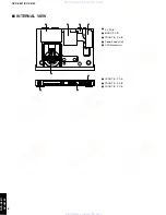
Power supply unit
DVD mechanism
Front panel
1103
1105
1102
1101
FRONT (2) P.C.B.
FRONT (3) P.C.B.
View A
CN3
1207
1301
1205
CN1
MONO P.C.B.
AV P.C.B.
1200
(FRONT P.C.B.)
FRONT (1) P.C.B.
FRONT (4) P.C.B.
1200
(AV P.C.B.)
A
Unlock
Flexible flat cable
Flatblade screwdriver
Bottom side
Tray
Top Cover [240]
Remove 5 screws [250] (2 on sides and 3 on
rear side).
Lift cover from rear side to remove.
DVD Mechanism [1300-1]
Solder the lands of the optical pick up. (Fig. 3)
Unlock tray cover ass'y and close tray.
Remove 4 screws (DVD mechanism to frame).
Lift DVD mechanism up slightly and move it backward
to remove.
MONO P.C.B. [1003]
Solder the lands of the optical pick up. (Fig. 3)
AV P.C.B. [1002]
Remove 3 cable connections [1100] [1200 (AV P.C.B.)]
[1201 (AV P.C.B.)].
Remove 3 screws [260] (P.C.B. to rear panel).
Release 2 locking spacers (P.C.B. to frame).
Dismount P.C.B..
Power Supply Unit [1005]
Remove 3 cable connections [CN101] [CN1] [CN3].
Remove 2 screws [256] (P.C.B. to frame).
Release 2 locking spacers (P.C.B. to frame).
Dismount power supply unit.
FRONT (1) P.C.B. [1001 (1)]
Remove 4 screws [260] (P.C.B. to front
panel).
Dismount P.C.B..
FRONT (3) P.C.B. [1001 (3)]
Remove 2 screws [260] (P.C.B. to front
panel).
Dismount P.C.B..
FRONT (2) P.C.B. [1001 (2)]
Remove 2 screws [260] (P.C.B. to front
panel).
Dismount P.C.B..
Remove cable connection [1200
(FRONT P.C.B.)].
Front Panel [101]
Remove 4 cables connections. [1105] [1205] [CN3] [1301]
Open tray. (Fig. 2)
Unlock tray lid and close tray.
Remove 2 screws [251] (Front panel to frame).
Unlock front panel by releasing successively 4 snaps (2 on sides
and 2 on bottom side).
Mounting
Dismounting
See REPLACEMENT PARTS LIST for item numbers.
2.7 mm
When disassembling, use T10 TORX screwdriver as shown below.
T10
Remove 7 cable connections [1101] [1102] [1103] [1105]
[1201 (MONO P.C.B.)] [1205] [1207].
Remove 3 screws [256] (P.C.B. to frame).
Remove screw [260] (P.C.B. to rear panel).
Dismount P.C.B..
Remove 3 cable connections [1101] [1102] [1103].
Open tray. (Fig. 2)
FRONT (4) P.C.B. [1001 (4)]
Remove cable connection [1301].
Remove 2 screws [260] (P.C.B. to rear panel).
Dismount P.C.B..
How to manually eject the tray
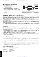
Preventive measure for laser diode from
electrostatic breakdown
Cable connections
Fig. 3
Fig. 1
Fig. 2
When replacing the MONO P.C.B. or DVD
mechanism, solder between lands of the optical
pick up P.C.B. to protect the laser diode against
electrostatic breakdown.
Notes
• Use an anti-static soldering iron to short-
circuit and unshort-circuit laser diode.
• After you have finished repairing, remove the
solder from the short-circuit location.
a. Move the slider in the direction indicated with a flatblade
screwdriver until the tray is ejected.
b. Gently pull the tray out.
w w w . x i a o y u 1 6 3 . c o m
Q Q 3 7 6 3 1 5 1 5 0
9
9
2
8
9
4
2
9
8
T E L
1 3 9 4 2 2 9 6 5 1 3
9
9
2
8
9
4
2
9
8
0
5
1
5
1
3
6
7
3
Q
Q
TEL 13942296513 QQ 376315150 892498299
TEL 13942296513 QQ 376315150 892498299


