background image

2

A

B

C

D

E

F

G

H

I

J

1

3

4

5

7

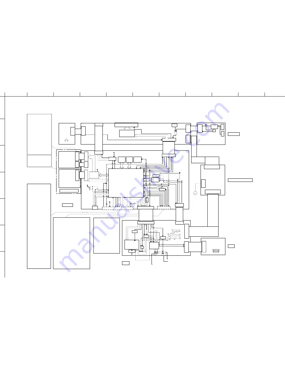
DVD-S663/DV-S6165

6

16

BLOCK DIAGRAM

AC IN

Interface between Loader Ass'y (KMH3133A) and MPEG:

Interface between MPEG and AV:

Interface between AV and MPEG:

SD10.1

MPEG

Class6, 4L

SDRAM

8MX16

Flash

2MX8

E2PROM

IR (109)

Fnt_irqN (FRT_STB)

AV

Class 3, 2L

S2,  SEL_{1:0}
ipod_rx, ipod_tx

3V3

MOTOR
DRIVER

AM5888S

24P 0.5 FFC H

6P PH V 

5P PH V

1    GND
2    LD_DVD
3    NC
4    HFM
5    MD
6    LD_CD
7    VR_DVD
8    VR_CD
9    NC
10  E
11  VCC
12  VC
13  GND
14  F
15  B
16  A
17  RF
18  CD/DVD
19  D
20  C
21  T-
22  T+
23  F+
24  F-

1    SP-
2    SP+
3    L_SW
4    L_SW
5    SLED-
6    SLED+

CON V 8P M 2.50

HDMI

SPDIF_o

Line_Det/ioex_irqN

MT1389S

KHM313AAM

ASA LOADER

WXD8829

SCL0, SDA0

5P PH H

1    VSYNC
2    HDMI_INT
3    HSYNC
4    GND
5     SPDIF
6    +5V_STBY
7    DSD_LFE
8    +5VL
9    PCM_LR (DSD_L)
10  +3V3_HDMI  
11  PCM_LsRs (DSD_Ls)
12  +3V3_HDMI
13  PCM_Clfe (DSD_C)
14  +3V3_HDMI
15  PCM_Cs (DSD_R)
16  +3V3_HDMI
17  PCM_LtRt (DSD_Rs)
18  GND
19  PCM_LRCK
20  GND 
21   PCM_BCLK (DSD_CLK) 
22   GND
23   PCM_MLK
24   GND
25   GND
26   GND
27   VCLK
28   GND
29   Y0
30   GND
31   Y1
32   GND
33   Y2
34   GND
35   Y3
36   GND
37   Y4
38   GND
39   Y5
40   GND
41   Y6
42   GND
43   Y7
44   GND
45   SCL_1
46   GND
47   SDA_1
48   CEC_WAKEUP
49   CEC
50   CEC_INT

CEC

 CEC_DET

SCL1 (VSCK), SDA1 (VSDA)

+5V_STBY,

3V3_stby,

+5VL

+5V_stby

+5VL

GPO_0

V_CLK

VSYNC

8bit ITU601

HSYNC

CEC_IrqN

S{1:0}

AV_MuteN

HDMI_intN

DAC_rstN

21P 1.25 FCC H

30P 1.25 FFC H

Line_in

Mic_in/GPIO

HP_Det

Spdif_i/Line_i

MCKi/BCKi/LRCKi

SCART

VIDEO OUT

AUDIO

OUT

CS8416

YPbPr/sY/sC/CVBS

BH7868

Video 6dB

LPF

S0

S1

S1

S2

P8

P16

Stby_ctl

S1

Trans

MCK,BCK,LRCK

St ereo DAC

AK4385

Opamp+LPF

LtRt

AHC125

Buffer

AHC125

Buffer

+5V

+12V

-12V

-9Va

-12Va

+5Vstby

+12Va

+9Va

+5VL

Stby_ctl

150mA

50mA

1300mA

300mA

50mA

30P 1.25 FFC H

RGB

Coax

Opt

Power Supply Unit

Front (1) Display

FRONT (2)
Standby/ON

2P EH H

2P 2.50

DIPMATE

5P 2.50

DIPMATE

8P EH V

8P 2.50 DIPMATE

VFD

5P EH V

2P

3P 2.50

DIPMATE

3P EH H

IR_OUT

IR_IN

FRONT (3) IR link

1   +5V_STBY
2   GND
3   EXT_IR

8P EH V

9P EH V

9P EH V

Stby_psu

Stby_det

1V8

3V3A

+3V3_stby

VSDA/VSCK/VSTB

Stby_det

PCM_LRCK

IR

Opto-

Coupler

Ext_IR

IR

USB

connector

USB_en

5P PH V

USB_oc

+5VL

Ext_IR

Trans

+5V_STBY

HPD

+5V_stby

CEC

Current

Limiter

DP,DM

5V_Vbus

1  5V_Vbus
2  DM
3  DP
4  GND
5  GND(shield)

1 Stby_ON
2 GND

1  GND
2  +12VA
3  GND
4  +5V
5  -24V

1  VSDA/SDA_1
2  VSCK/SCL1
3  Fnt_Stb
4  GND

5  IR

6  LRCK/GND
7  +5VL
8  Stby_Det

50P 0.5 FFC SM H

1  +5V
2  GND
3  +5V
4  GND
5  +12VA
6  +5V
7  -12VA
8   NC

 CEC_WakeUP

DAC_STB/SEL_0

SPDIF_o

PCM{4:1}/DSD{6:1}/

MCK/BCK/LRCK

1   Stby_PSU
2   +5VL
3   +5VL
4   GND
5   GND
6   NC
7   +5V_MTK
8   +5V_MTK
9   +12VL_A

27k

3V3A for Pin 190/195(VideoDACVDD),

216(Audio CLK VDD)

228(DACVDD)

243(PLLVDD)

248(ADCVDD)

Pin 234 is 1V8 specially for SACD

1     PCM_LRCLK
2     GND
3     PCM_BCLK
4     Vsel/P50
5     PCM_data4(PCM_LtRt)
6     D2_5V
7     NC
8     DPDET
9     NC
10   GND
11   PCM_MCLK
12   MUTE_CTRL_1
13   VSCK
14   DAC_RST
15   VSDA
16   DAC_STB
17   SPDIF_OUT
18   S0
19   S/Y DAC_RST
20   S1
21   S/C
22   Y/C_REF
23   CVBS
24   CVBS_REF
25   Y
26   Y_REF
27   Pb
28   Pb_REF
29   Pr
30   Pr_REF

1    GND
2    AUX_IN  
3    TV_muteN
4    AV_irqN(Chgr_irqN)
5    GND
6    SPDIF_i  
7    GND  
8    UART_Rx  
9    UART_Tx(Line_det) 
10  GND
11  SCL0
12  SDA0
13  GND
14  DAC_rstN
15  USB_Enb
16  stby_det(HP_det)
17  stby_psu
18  sel_1
19   sel_0
20  S2(DC_err)
21  GND

TMDS,DDC

Regulator
(AM588S)

1.8V
PNP

3.3V
PNP

3.3V

Regulator

1   LOAD+
2   LOAD-
3   GND
4   TROUT
5   TRIN

MCU_irqN

+5V_stby

Vsel

YPbPr

TS5V330

Video SW

sY, sC, CVBS

D2_line2/D2_Dpdet

PT6312

VFD Driver

PCM LtRt

10P FFC  V

D2 (J model)

(G, F models)

(U, K, A, G, F, L, P models)

10P FFC  V

(U, K, A, G, F, L, P models)

(J model)

MPEG

Power Supply Unit 

AV

Loader Ass'y

FRONT

• See page 30, 31 

 SCHEMATIC DIAGRAM

• See page 26, 27 

 SCHEMATIC DIAGRAM

• See page 28, 29 

 SCHEMATIC DIAGRAM

• See page 33 

 SCHEMATIC DIAGRAM

D2

• See page 32 

 SCHEMATIC DIAGRAM

1302

7301

CN3

CN1

CN101

1303

1301

1103

7102

1102

1100

1104

1200

1100

1101

7103

1102

1201

1200

7110

7111

7216

7205

7212

7105

7202

7201

7203

1204

1100

7112

7122

7121

7213

7214

7238

1202

1103

1101

1102

1101

7125

1109

1100

1101

1200

1211

1201

1202

1110

7100

1101

7300

Summary of Contents for DV-S6165

Page 1: ...nit s indicated on the cover The research engineering and service departments of YAMAHA are continually striving to improve YAMAHA products Modifications are therefore inevitable and specifications are subject to change without notice or obligation to retrofit Should any discrepancy appear to exist please contact the distributor s Service Division WARNING Static discharges can destroy expensive co...

Page 2: ...eam for several seconds to detect if a disc is present During this time 5 10 sec the laser may radiate through the lens of the laser pick up unit Do not attempt any servicing during this period If no disc is detected the laser will stop emitting the beam When a disc is loaded you will not be exposed to any laser emissions 2 The laser power level can be adjusted with the VR on the pick up PWB howev...

Page 3: ... 10 mW VCD CD ビーム広がり 60度 Warning for power supply The primary side of the power supply carries live mains voltage when the player is connected to the mains even when the player is switched off This primary area is not shielded so it is possible to accidentally touch copper tracks and or components when servicing the player Service personnel have to take precautions to prevent touching this area or...

Page 4: ...ged by static electricity in the working environment Only attempt service after ensuring that all grounding procedures have been completed 1 Worktable grounding Put a grounded conductive material sheet or iron sheet on the area where the optical pickup is placed 2 Human body grounding Use an anti static wrist strap to discharge the static electricity from your body 1M ohms Conductive material shee...

Page 5: ...DVD S663 DV S6165 5 DVD S663 DV S6165 FRONT PANELS DVD S663 U K A G F L P J models DV S6165 U model REAR PANELS DVD S663 U model DVD S663 K model ...

Page 6: ...DVD S663 DV S6165 DVD S663 DV S6165 6 DVD S663 G model DVD S663 F model DVD S663 L model DVD S663 P model DVD S663 J model DVD S663 A model ...

Page 7: ...DVD S663 DV S6165 7 DVD S663 DV S6165 REMOTE CONTROL PANEL DV S6165 U model DVD 16 ...

Page 8: ...0 Hz Number of lines 625 525 Playback Multistandard PAL NTSC CONNECTIONS 接続端子 Video output RCA Phono x 1 yellow S video output Mini DIN 4 pins x 1 Component video output U K A G F L P models Y output RCA Phono x 1 green PB CB PB output RCA Phono x 1 blue PR CR PR output RCA Phono x 1 red SCART Euroconnector x 1 G F models Audio output L R RCA Phono x 1 pair white red Digital output Coaxial RCA Pho...

Page 9: ...d is intended for home and other limited viewing uses only unless other wise authorized by Macrovision Reverse engineering or disassembly is prohibited 本製品は 著作権保護技術を採用しており 米国特許及びその他の知的 財産権によって保護されています この著作権保護技術の使用は マク ロビジョンの許可が必要で またマクロビジョンの特別な許可がない限 り家庭用及びその他の一部の視聴用の使用に制限されています 分解し たり 改造することも禁じられています HDMI the HDMI logo and High Definition Multime dia Interface are trademarks or registered trade m...

Page 10: ...Loader Ass y 6 FRONT 2 P C B 7 FRONT 1 P C B 8 USB Connector 9 6 下記のユニットは 小部品の部品供給はできません 故障の場合は 各ユニットを交換してください ローダーASSY MPEG P C B FRONT P C B AV P C B D2 P C B J model 電源ユニット None of the components of the following units can be supplied separately Each unit must be replaced as a whole in case of a failure Loader Ass y MPEG P C B FRONT P C B AV P C B Power Supply Unit ...

Page 11: ...fter activating TRADE mode it is not possible to operate keys of this unit as usual except the follow ing key STANDBY ON key Turn on the power only But operation with the remote control is available as usual After TRADE mode is activated initial settings for repeat reproduction of this unit are as follows DVD RPT TT repeat title VCD SVCD CD RPT ALL repeat all TRADE MODE トレードモード 本機には OPEN CLOSE キーを...

Page 12: ...ay opens after about 2 second 2 Press the 2 5 and 9 keys on the remote con trol in that order Fig 4 3 TRA OFF is displayed and TRADE mode is can celled About 2 seconds later the disc tray is closed automatically Fig 5 トレードモードの解除 トレードモードを解除する前に 本機の電源を入れま す 1 リモコンの STOP キーを押し続けます Fig 4 約2秒後 ディスクトレイが開きます 2 リモコンの 2 5 9 のキーを押します Fig 4 3 TRA OFF が表示され トレードモードが解除さ れます 約2秒後 ディスクトレイが自動的に閉じ ます Fig 5 Cancel ...

Page 13: ...crews 250 P C B to front panel Dismount P C B Remove cable connection 1200 FRONT P C B Front Panel Ass y 1 Remove 4 cables connections 1110 1209 CN3 1301 Open disc tray Fig 2 Unlock tray cover ass y and close disc tray Remove 2 screws 267 Front panel to bottom Unlock front panel ass y by releasing successively 4 snaps 2 on the side and 2 on the bottom Mounting Dismounting See REPLACEMENT PARTS LIS...

Page 14: ...2 P C B 1006 ケーブルの接続を外します 1100 D2 P C B P C B をリアパネルに取り付けているネジ 250 2本を 外します P C B を取り外します ケーブルの接続3本を外します CN101 CN1 CN3 P C B をフレームに取り付けているネジ 256 2本を 外します P C B をフレームに取り付けているスペーサー2箇所を ゆるめます 電源ユニットを取り外します P C B をフロントパネルに取り付けて いるネジ 250 4本を外します P C B を取り外します ケーブルの接続を外します 1104 P C B をフロントパネルに取り付けて いるネジ 250 2本を外します P C B を取り外します ケーブルの接続を外します 1200 FRONT P C B ケーブルの接続を外します 1110 1209 CN3 1301 ディスクトレイを開きます ...

Page 15: ...スト 指定されたキーを押すと 表示が下記のように変わり ます Canceling Test Mode Disconnect the power cable from the AC power outlet テストモードの解除 ACコンセントから電源コードを抜きます OFF OFF ON OFF ON OFF Initial display 初期表示 Press PLAY key of this unit 本機の PLAY キーを押します All segments on 前セグメント点灯 Press PLAY key of this unit 本機の PLAY キーを押します Lighting of segments in lattice セグメント格子状点灯 Press STOP key of this unit 本機の STOP キーを押します Press OPEN CLOSE key ...

Page 16: ..._IN FRONT 3 IR link 1 5V_STBY 2 GND 3 EXT_IR 8P EH V 9P EH V 9P EH V Stby_psu Stby_det 1V8 3V3A 3V3_stby VSDA VSCK VSTB Stby_det PCM_LRCK IR Opto Coupler Ext_IR IR USB connector USB_en 5P PH V USB_oc 5VL Ext_IR Trans 5V_STBY HPD 5V_stby CEC Current Limiter DP DM 5V_Vbus 1 5V_Vbus 2 DM 3 DP 4 GND 5 GND shield 1 Stby_ON 2 GND 1 GND 2 12VA 3 GND 4 5V 5 24V 1 VSDA SDA_1 2 VSCK SCL1 3 Fnt_Stb 4 GND 5 I...

Page 17: ...3 4 5 6 7 8 11 12 13 14 15 16 17 18 19 2 20 8 9 1XXX 1 10 1109 1 10 2 3 4 5 6 7 5 6 7 8 9 HLEM10S 1R HLEM10S 1R 1 10 2 3 4 1 2 3 4 5 6 7 8 1100 5 6 7 8 1212 319804002080 1209 1 2 3 4 1 2 3 4 5 6 7 8 7 8 9 1102 25 26 27 28 29 3 30 4 5 6 15 16 17 18 19 2 20 21 22 23 24 1100 1 10 11 12 13 14 1 2 1103 B03B PASK 1 2 3 319804000020 1104 1 2 3 1 2 3 4 5 B03B PASK 1301 CN3 1 2 3 4 5 1101 440054 5 5 6 7 8 ...

Page 18: ...AILABLE The first digit of a component indicates the component type 1xxx Connector 3xxx Resistor 5xxx Coil 7xxx IC Transistor FET 2xxx Capacitor 4xxx SMD jumper 6xxx Diode 9xxx Wire jumper Loader Ass y Loader Ass y Loader Ass y FRONT 1 1102 USB connector AV 1100 AV 1201 MPEG Top view HDMI ...

Page 19: ...663 DV S6165 The first digit of a component indicates the component type 1xxx Connector 3xxx Resistor 5xxx Coil 7xxx IC Transistor FET 2xxx Capacitor 4xxx SMD jumper 6xxx Diode 9xxx Wire jumper MPEG Bottom view ...

Page 20: ...ansistor FET 2xxx Capacitor 4xxx SMD jumper 6xxx Diode 9xxx Wire jumper Power Supply Unit CN1 MPEG 1212 D2 J model 1100 MPEG 1202 AV SCART VIDEO S VIDEO COAXIAL COMPONENT Y PR CR PB CB AUDIO OUT DIGITAL OUT L R AV Top view OPTICAL J model G F models U K A L P J models U K A G F L P models U K A G F L P models DIGITAL OUT VIDEO OUT ...

Page 21: ...S663 DV S6165 The first digit of a component indicates the component type 1xxx Connector 3xxx Resistor 5xxx Coil 7xxx IC Transistor FET 2xxx Capacitor 4xxx SMD jumper 6xxx Diode 9xxx Wire jumper AV Bottom view ...

Page 22: ...onnector 3xxx Resistor 5xxx Coil 7xxx IC Transistor FET 2xxx Capacitor 4xxx SMD jumper 6xxx Diode 9xxx Wire jumper FRONT 2 1200 OPEN CLOSE HDMI indicator PLAY PAUSE STOP PROGRESSIVE indicator FRONT 1 FRONT 1 FRONT 3 1301 Power Supply Unit CN3 MPEG 1209 Bottom view Top view DISPLAY DISPLAY ...

Page 23: ... Connector 3xxx Resistor 5xxx Coil 7xxx IC Transistor FET 2xxx Capacitor 4xxx SMD jumper 6xxx Diode 9xxx Wire jumper FRONT 1 1104 FRONT 2 FRONT 2 Bottom view FRONT 3 Bottom view Top view FRONT 3 Top view STANDBY ON STANDBY ON IR LINK STANDBY ON IR LINK FRONT 1 1103 REMOTE CONTROL OUT IN ...

Page 24: ...git of a component indicates the component type 1xxx Connector 3xxx Resistor 5xxx Coil 7xxx IC Transistor FET 2xxx Capacitor 4xxx SMD jumper 6xxx Diode 9xxx Wire jumper D2 Top view J model J model D2 Bottom view AV 1109 D1 D2 VIDEO OUT ...

Page 25: ...A B C D E F G H I J 1 2 3 4 5 6 7 DVD S663 DV S6165 25 POWER SUPPLY UNIT Top view POWER SUPPLY UNIT Bottom view FRONT 1 1101 AV 1200 AC IN ...

Page 26: ...9 117 116 144 155 154 153 152 151 150 135 146 136 111 132 130 GPIO20 SD_CMD 112 GPIO21 SD_CLK 110 GPIO22 SDD0 INT 140 141 139 149 143 DRAM INTERFACE MT1389EXE S 7110 2 137 138 134 147 F128 100n 2109 100n 5 3 2 4 1 2148 NCP303LSN23 7112 F131 100n 2161 EN_ 4 1 GND 2 3 5 OC_ 6 7 8 7111 TPS2051BD 1 3 2 F130 7104 BC817 25W 100K 3109 4127 100n 2101 BLM18P 5100 60R 5 4 100u 2119 33R 3173 4 100n 2155 BC81...

Page 27: ...501100A 1 10 11 12 13 14 470n 5202 4243 D 4223 5201 470n 4260 4258 10p 2249 4234 F258 BC817 25 7216 F257 F234 F231 4219 4227 4218 22p 2213 2269 22p F246 4203 F248 4224 D 7215 BC817 25 27R 3282 4K7 3269 150R 3201 3238 470R 47p 2228 F266 F209 F267 F254 2 3236 10K BSN20 7209 3 1 BLM18P 5208 60R 11 12 13 16 17 26 6 23 21 25 27 24 9 5 4 3 2 1 10 14 15 18 7 22 8 20 19 28 7203 CS8416 CZ DIG AUDIO IF Φ RE...

Page 28: ...00u 2169 6109 BZX384 C15 16V GND T152 GND 47p 2191 GND GND GND GND GND 2188 220p 3161 47K 3129 10K 10n 2176 22u 2146 3 4 5 6 7 8 9 16V HLEM10S 1R 1109 1 10 2 6108 BAS316 GND GND 4102 GND GND GND T137 T126 4105 2189 22u 6 3V T106 75R 75R 3176 GND 3185 4109 GND 220p 2159 10K 3150 75R 3187 2156 100n T155 GND 2 3 1 5 4 1u0 2187 74AHC1G125 7122 T133 7116 1 3 2 T122 BC817 40 GND 68R 3177 GND GND 2163 10...

Page 29: ...S316 220R 3286 3251 22R GND 10K 3254 T217 4203 3287 330R 7246 BC817 25 6218 3203 22K BAS316 T203 3217 100n 2266 2220 470n 5K1 AGND 4210 GND GND 5V 6220 BAS316 6217 BAS316 3241 470R 100R 3218 2 3 6 7 8 4 5 1 7240 L78L05ACD 33R 3210 5 6 7 8 4 8 4 MC33078D 7214 2 MC33078D 7214 1 3 2 1 3235 2271 12p 33R 3255 2K2 2262 12p 4201 33R 3298 4205 2 2214 680p BC817 40 7208 1 3 2228 25V100u 3223 4K7 T215 T216 ...

Page 30: ... P13 16 17 P14 P15 18 5 P2 P3 6 7 P4 P5 8 9 NC1 19 20 21 22 NC6 30 P1 4 13 P10 P11 14 15 25 5G 6G 24 23 7G 1 F1_1 F1_2 2 F2_1 31 F2_2 32 3 7 BT 299GNK 1100 29 1G 2G 28 27 3G 4G 26 1 2 3 1103 WH03D 1 1 2 3 4 5 4K7 3104 1101 WH05D 1 7104 BC857B LTL 8166FTNN BC847B 7103 6121 100K 3131 3116 47R 3101 10K T115 1107 T116 22R 3152 3142 100K 6101 PDZ5 6 B T101 BZX384 C5V6 6109 1K0 3105 100K 3135 3139 T105 ...

Page 31: ...0 B4 2301 B1 2302 B4 2303 A4 1 2 3 4 1 2 3 4 A B A B 2304 A1 3301 B2 3302 A4 3303 B3 3304 A1 7300 A3 7301 B2 T310 A1 T311 A1 T312 B1 T313 A4 T314 A4 T315 A4 T310 T311 T315 T312 T313 310310126941 1320 T314 2304 1310 310310126941 3304 470R 25V 10u 10 2 2303 10p 1302 MSJ 035 12A PC 1 10p 2302 3302 10K 4 3 2 5V_STBY 2 EL816 7300 1 MSJ 035 12A PC 1303 1 10 2 3 5V_STBY 319804002030 1301 1 100n 2301 10K ...

Page 32: ...1 1101 A4 2101 B3 2102 B3 2103 B3 3101 B3 6101 B2 6102 B3 6103 B3 1 2 3 4 1 2 3 4 A T101 A1 T102 A1 T103 A1 T104 A1 T105 A1 T106 A1 T107 A1 BZX384 C4V7 6103 6101 BZX384 C4V7 6102 T106 T107 BZX384 C4V7 T104 T105 T102 T103 2103 T101 220p 2102 220p 220p 2101 3101 8 9 15 16 10K 12 13 14 2 3 4 5 6 7 CSS0514 0801 1101 1 10 11 10 2 3 4 5 6 7 8 9 HLEM10S 1R 1100 1 Y2 DPDET 0 2 5 D2_5V V2 U2 GND to AV_1109...

Page 33: ...A B C D E F G H I J 1 2 3 4 5 6 7 DVD S663 DV S6165 33 POWER SUPPLY UNIT AC IN POWER TRANSFORMER to AV_1200 Page 29 D2 to FRONT 1 _1101 Page 30 D1 ...

Page 34: ...Black 3 x 15 S Tight Black 1 2 3 186 267 183 182 192 230 240 267 267 267 256 183 256 256 250 250 256 256 250 250 250 250 345 1001 1 1001 Front panel ass y Chassis EMC spring B 2 1002 8104 1003 1004 1004 1 1005 8009 8100 1006 1002 8103 J model G F models 250 J model G F models 256 U K A L P J model G F models 2000 No replacement part available サービス部品供給なし 1001 3 2002 Note The replacement battery cov...

Page 35: ...53440 PW HEAD TORX S TIGHT SCREW TI SI 3x6 MFNI33 3104 120 40081 PWヘッドSタイトネジ s 345 AAX53650 POWER CABLE 1 8m 2422 070 98255 J 電源コード 05 s 345 AAX47750 POWER CABLE 1 8m 2422 070 98235 UA 電源コード s 345 AAX59130 POWER CABLE 1 8m 2422 070 98222 K 電源コード s 345 AAX53630 POWER CABLE 1 8m 2422 070 98231 GFL 電源コード s 345 AAX82310 POWER CABLE 1 8m 2422 070 00026 P 電源コード 1001 AAX90350 P C B ASS Y FRONT 3139 248 5...

Page 36: ... 1 2 3 4 5 6 7 8 9 SUBTITLE 0 AUDIO ZOOM REPEAT REPEAT A B Key label Code 7C 80 7C B1 7C A6 7C B4 7C B5 7C B8 7C B6 7C B3 7C B2 7C AC 7C B9 7C 92 7C BA 7C 85 7C E6 7C 94 7C 95 7C 96 7C 97 7C 98 7C 99 7C 9A 7C 9B 7C 9C 7C AA 7C 93 7C AD 7C D7 7C A3 7C A4 1 2 3 4 5 7 6 8 9 11 13 12 14 16 17 18 19 20 21 22 23 24 25 26 27 28 29 30 15 10 1 2 3 4 5 6 7 8 9 10 11 12 13 14 15 16 17 18 19 20 21 22 23 24 25...

Page 37: ...DVD S663 DV S6165 ...

Reviews: