background image

DVD-S2300MK2

23

DVD-S2300MK2

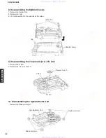
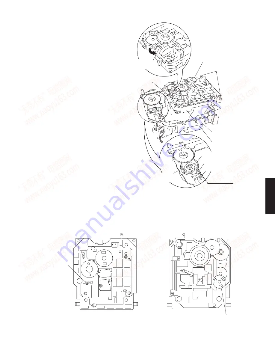
< P r e c a u t i o n s   i n   R e a s s e m b l i n g   t h e

Traverse Block>

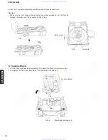
• T a k e   t h e   f o l l o w i n g   p r e c a u t i o n s   w h e n

reassembling the Traverse Block.

1. Turn Traverse Gear on the Traverse Block to let

trigger lever turn rightward.

2. Bring cam gear lever to the lever adjusting

position at the end of Mechanical chassis unit.

3. Put tabs A and B into slots A and B respectively.

Place tabs C into hooks to mount the Traverse
Block on Mechanical chassis unit. (Slot A...
Mechanical Chassis, Slot B... Cam Gear)

Mechanical chassis unit

Traverse block

Lever adjusting position

Cam gear

Slot B

Lever

Slot A

Tab A

Tab B

Hook

Tab C

Traverse Gear

Trigger Lever

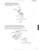
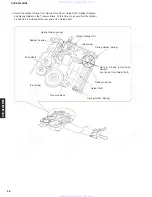
Note: The Traverse Gear B is under the Traverse Gear C.

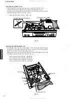
6. Traverse Gear B, C

1. Disengage the tabs from the Traverse Gear.
2. Remove the Traverse Gears B and C.

Tab of Traverse Gear

<Traverse block bottom>

Traverse Gears B and C

www. xiaoyu163. com

QQ 376315150

9

9

2

8

9

4

2

9

8

TEL 13942296513

9

9

2

8

9

4

2

9

8

0

5

1

5

1

3

6

7

3

Q

Q

TEL  13942296513  QQ  376315150  892498299 

TEL  13942296513  QQ  376315150  892498299 

http://www.xiaoyu163.com

http://www.xiaoyu163.com

Summary of Contents for DVD-S2300MK2

Page 1: ... to perform as specified For these reasons we advise all YAMAHA product owners that any service required should be performed by an authorized YAMAHA Retailer or the appointed service representative IMPORTANT The presentation or sale of this manual to any individual or firm does not constitute authorization certification or recognition of any applicable technical capabilities or establish a princip...

Page 2: ...n may result in hazardous radiation exposure Laser Emitting conditions 1 When the Top Cover is removed and the POWER SW is turned to the ON position the laser component will emit a beam for several seconds to detect if a disc is present During this time 5 10 sec the laser may radiate through the lens of the laser pick up unit Do not attempt any servicing during this period If no disc is detected t...

Page 3: ...HEN OPEN AVOID DIRECT EXPOSURETO BEAM DANGER FDA 21 CFR IEC60825 1 VISIBLE AND INVISIBLE LASER RADIATIONWHEN OPEN AVOID EXPOSURETO BEAM CAUTION RAYONNEMENT LASERVISIBLE ET INVISIBLE EN CAS D OUVERTURE EXPOSITION DANGEREUSE AU FAISCEAU ATTENTION SYNLIG OG USYNLIG LASERSTRÅLING VED ÅBNING UNDGÅ UDSÆTTELSE FOR STRÅLING ADVARSEL AVATTAESSA OLET ALTTIINA NÄKYVÄÄ JA NÄKYMÄTÖN LASERSÄTEILYLLE ÄLÄ KATSO S...

Page 4: ...erse Unit Optical Pickup 1 Handle the traverse unit optical pickup gently as it is an extremely high precision assembly 2 The flexible cable lines may break if an excessive force is applied to it Use caution when handling the cable 3 The semi fixed resistor for laser power adjustment should not be adjusted Do not turn the resistor 1M Conductive material sheet or iron sheet Anti static wrist strap ...

Page 5: ...OTE CONTROL PANEL U model www xiaoyu163 com QQ376315150 9 9 2 8 9 4 2 9 8 TEL 13942296513 9 9 2 8 9 4 2 9 8 0 5 1 5 1 3 6 7 3 Q Q TEL 13942296513 QQ 376315150 892498299 TEL 13942296513 QQ 376315150 892498299 http www xiaoyu163 com http www xiaoyu163 com ...
Page 6: ...Control terminal Power Supply U model AC 120 V 60Hz Power Consumption U model 35 W Standby Power Consumption 0 8 W Dimensions W x H x D 435 x 116 x 350 mm 17 1 8 x 4 9 16 x 13 3 4 Weight 9 0 kg 19 lbs 13 oz Finish Black Color U model Accessories Remote Control Batteries x 2 AA R6 UM 3 Audio Video Cable Power Cable Specifications are subject to change without notice due to product improvements U U ...

Page 7: ...AIN 3 P C B 8 TERMINAL P C B 9 DVD Mechanism 0 DVD Module P C B A SACD P C B 435 17 1 8 Unit mm inch 116 4 9 16 350 13 3 4 DIMENSIONS www xiaoyu163 com QQ376315150 9 9 2 8 9 4 2 9 8 TEL 13942296513 9 9 2 8 9 4 2 9 8 0 5 1 5 1 3 6 7 3 Q Q TEL 13942296513 QQ 376315150 892498299 TEL 13942296513 QQ 376315150 892498299 http www xiaoyu163 com http www xiaoyu163 com ...
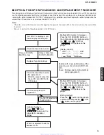
Page 8: ...al of Inner Cover a Remove 4 screws 3 and 2 screws 4 Fig 1 b Remove the inner cover Fig 1 3 Removal of Tray Lid a Remove the Gear for opening the tray from the DVD Mechanism and install it onto a Screwdriver to make a Gear Jig Fig 2 b Insert the Gear Jig into the tray open close hole Fig 3 c Turn the Gear Jig counterclockwise to open the tray Fig 3 d Remove the Tray Lid from the tray section Fig 4...

Page 9: ... iron to short circuit and unshort circuit laser diode After you have finished repairing the laser diode follow the correct procedure to remove the solder from the short circuit location d Disconnect the connectors CB1 and CB6 Fig 5 e Remove the DVD Mechanism 5 Removal of Front Panel Unit a Remove 4 screws 6 and 1 screws 7 Fig 7 b Remove 4 screws 8 Fig 7 c Disconnect the connectors CB10 CB602 CB60...

Page 10: ...UDIO 1 P C B Fig 9 7 Removal of SACD P C B a Disconnect the connectors CB3 CB12 CB14 Fig 9 b Remove the SACD P C B with the tip of the 4 Support pinched with pliers or the like Fig 9 8 Removal of Support P C B a Remove 1 screws A Fig 8 b Remove 5 screws B and then remove the Support P C B Fig 10 www xiaoyu163 com QQ376315150 9 9 2 8 9 4 2 9 8 TEL 13942296513 9 9 2 8 9 4 2 9 8 0 5 1 5 1 3 6 7 3 Q Q...

Page 11: ...nd E and remove 2 screws F and then remove the MAIN 1 P C B Fig 12 Checking the SACD P C B After removing the top cover and inner cover remove the SACD P C B Set the SACD P C B upright with its right side upward Fig 13 Replace the cables connected to the SACD P C B with the following extension cables for servicing Fig 13 35 pin extension cable 200mm MFA35200 15 pin extension cable 200mm MFA15200 w...

Page 12: ...5200 26 pin extension cable JGS0098 TX946370 22 pin extension cable JGS0116 AAX16610 Fig 15 Yellow White Extension cable CB508 Connect with care to the polarity Checking the AUDIO P C B After removing the top cover and inner cover remove the AUDIO P C B Set the AUDIO P C B upright with its rear panel side upward Fig 14 Disconnect the cable connected to the AUDIO P C B and then reconnect it via the...

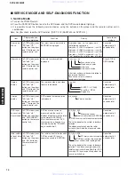
Page 13: ... SCREEN button on the remote control unit while pressing the and DVD or CD buttons on the player Writing method Press the button on the remote control unit while pressing and buttons on the player OPTICAL PICKUP SELF DIAGNOSIS AND REPLACEMENT PROCEDURE An optical pickup self diagnosis function and tilt adjustment check function have been included in this unit When repairing use the following proce...

Page 14: ...ds later and ON SCREEN value stored in EEPROM button on the remote After the measurement DVD control unit laser emission is kept on It is The value denotes the current in decimal turned off when the POWER notation key is switched off The above example shows the initial current is 34mA and the measured value is 32mA Initial setting In STOP mode press The initial current value for each LDO_034_028 C...

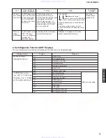
Page 15: ...he player initialization buttons on the player for 3 seconds or longer Measured current Initial current stored in EEPROM CD laser current measurement mode 2 Self Diagnosis Function UHF Display This unit incorporates a convenient self diagnosis function for use in troubleshooting Display method Display Diagnosis Service numbers U11 Focus error displayed during use H01 Tray loading error H02 Spindle...

Page 16: ...Press DIMMER on remote control unit Press REPEAT on remote control unit Press A B on remote control unit Press STOP on remote control unit Press VIDEO OFF on remote control unit Press 1 on remote control unit Press 2 on remote control unit Press 3 on remote control unit Press 4 on remote control unit Press 5 on remote control unit Press 6 on remote control unit Press 9 on remote control unit Press...

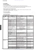
Page 17: ...e recovery procedure is performed the user settings will be erased and the factory settings will be restored as when the initialization procedure is used Therefore it is necessary to write down the content of the user settings before performing the recovery procedure and reset it after that 5 2 Firmware Version Up of the DVD Module The firmware of the DVD module may be updated to improve the quali...

Page 18: ...dress is obtainable in the CD system ODC IC2001 F612 No CRC OK is issued for a certain time No ID data is obtainable in the DVD system ODC IC2001 F630 No response is provided for the inquiry of KEY DET Only when used internally F631 CPPM KEY DET is not usable until the end of the file The CPPM file system cannot be read due to a scratch etc Disc CPPM 1 F632 CPPM KEY DET is not usable CPPM KEY DET ...

Page 19: ...er from the motor connections 3 Remove the connectors Solder Connector Screw Screw Terminal P C B Connector Mechanism unit bottom www xiaoyu163 com QQ376315150 9 9 2 8 9 4 2 9 8 TEL 13942296513 9 9 2 8 9 4 2 9 8 0 5 1 5 1 3 6 7 3 Q Q TEL 13942296513 QQ 376315150 892498299 TEL 13942296513 QQ 376315150 892498299 http www xiaoyu163 com http www xiaoyu163 com ...

Page 20: ... remove the Clamp Plate Unit Tab Tab Clamp Plate Unit Stopper Stopper Tab Clamp Plate Unit Stopper www xiaoyu163 com QQ376315150 9 9 2 8 9 4 2 9 8 TEL 13942296513 9 9 2 8 9 4 2 9 8 0 5 1 5 1 3 6 7 3 Q Q TEL 13942296513 QQ 376315150 892498299 TEL 13942296513 QQ 376315150 892498299 http www xiaoyu163 com http www xiaoyu163 com ...
Page 21: ...on back of the Tray and that of concave phase on Drive Gear Lever Cam Gear Mechanical Chassis Unit Lever adjusting point Back of the Tray Convex phase Traverse Gear Tray Concave phase Drive Gear Drive Gear Tray a Place the Tray on the unit from rearward Tray www xiaoyu163 com QQ376315150 9 9 2 8 9 4 2 9 8 TEL 13942296513 9 9 2 8 9 4 2 9 8 0 5 1 5 1 3 6 7 3 Q Q TEL 13942296513 QQ 376315150 89249829...

Page 22: ...ble and Tray becomes 5mm or less Tray Turntable 5mm or less 5 Traverse Block 1 Lift the Traverse Block while spreading the Hook of the Mechanical chassis unit 2 Disengage the Tabs from the holes of the Mechanical chassis unit www xiaoyu163 com QQ376315150 9 9 2 8 9 4 2 9 8 TEL 13942296513 9 9 2 8 9 4 2 9 8 0 5 1 5 1 3 6 7 3 Q Q TEL 13942296513 QQ 376315150 892498299 TEL 13942296513 QQ 376315150 89...

Page 23: ...s unit Slot A Mechanical Chassis Slot B Cam Gear Mechanical chassis unit Traverse block Lever adjusting position Cam gear Slot B Lever Slot A Tab A Tab B Hook Tab C Traverse Gear Trigger Lever Note The Traverse Gear B is under the Traverse Gear C 6 Traverse Gear B C 1 Disengage the tabs from the Traverse Gear 2 Remove the Traverse Gears B and C Tab of Traverse Gear Traverse block bottom Traverse G...

Page 24: ... using the soldering iron without anti static feature short circuit the Flexible Cable terminal with a clip before short circuiting the land After completing the repair remove the solder from the laser diode shorting jumper properly following the procedures described in this Manual Optical Pickup Unit Flexible Cable Use a clip or other item to ground the unit 7 Optical Pickup Unit 1 Remove the Scr...

Page 25: ...t FPC 7 2 Disassembling the Optical Pickup Unit 1 Remove 2 screws A and remove the TRV feed rack 2 Remove the screw B and remove the Terminal FPC 3 Remove the Optical Pickup Screw A TRV feed rack Optical Pickup Terminal FPC Screw B Fig A Connector Terminal FPC Ground the Optical Pickup with a Clip www xiaoyu163 com QQ376315150 9 9 2 8 9 4 2 9 8 TEL 13942296513 9 9 2 8 9 4 2 9 8 0 5 1 5 1 3 6 7 3 Q...

Page 26: ...uide Shaft Rubber Cushion and Spring Holder on the Traverse Block At this time make sure that the Optical Pickup Unit is installed at the rear end of the Guide Shaft Optical Pickup installation position rear end of the Guide Shaft www xiaoyu163 com QQ376315150 9 9 2 8 9 4 2 9 8 TEL 13942296513 9 9 2 8 9 4 2 9 8 0 5 1 5 1 3 6 7 3 Q Q TEL 13942296513 QQ 376315150 892498299 TEL 13942296513 QQ 3763151...

Page 27: ...Optical Pickup Unit Cutting Line Antistatic FPC www xiaoyu163 com QQ376315150 9 9 2 8 9 4 2 9 8 TEL 13942296513 9 9 2 8 9 4 2 9 8 0 5 1 5 1 3 6 7 3 Q Q TEL 13942296513 QQ 376315150 892498299 TEL 13942296513 QQ 376315150 892498299 http www xiaoyu163 com http www xiaoyu163 com ...
Page 28: ...sembling the Spindle Motor Unit Remove the Rubber Isolators 9 Disassembling the Traverse Gear A FG Unit 1 Remove the screw 2 Remove the Traverse Gear A Spindle Motor Unit Rubber Isolators Rubber Isolators www xiaoyu163 com QQ376315150 9 9 2 8 9 4 2 9 8 TEL 13942296513 9 9 2 8 9 4 2 9 8 0 5 1 5 1 3 6 7 3 Q Q TEL 13942296513 QQ 376315150 892498299 TEL 13942296513 QQ 376315150 892498299 http www xiao...
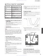
Page 29: ...on the front display For your information yyy and zz shown to the right have nothing to do with the jitter value yyy is the error counter while zz is the focus drive value Note Jitter value appears on the front display 4 Play test disc track01 inner periphery 5 Adjust tangential adjustment screw so that the jitter value is minimized 6 Play test disc track43 outer periphery 7 Adjust tilt adjustment...

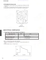
Page 30: ...cilloscope to the S video output Y terminal and terminate at 75 ohms 2 Confirm that the Y level is 1 0 Vp p 20 mV 1 Video Output Luminance Signal Confirmation Measurement point Mode Disc S Video output terminal Y OUT PLAY DVDT S15 Title 10 DVDT S01 Title 48 Color bar 100 Measuring equipment tools Confirmation value Screwdriver Oscilloscope 1 0 Vp p 20mV 200mV div 10µsec div www xiaoyu163 com QQ376...

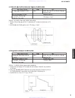
Page 31: ... output compatibility 1 Connect the oscilloscope to the component video output Y terminal and terminate at 75 ohms 2 Press the PROGRESSIVE button on the remote control unit The main unit is in the PROGRESSIVE output mode and the front panel indicator lights 3 Confirm that the Y level is 1 0 Vp p 20 mV Measurement point Mode Disc Component video output terminal PLAY DVDT S15 Title 10 DVDT S01 Title...

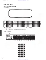
Page 32: ...te 1 F1 F2 Filament 5 DL Datum Line 2 NP No pin 6 1G 14G Grid 3 NX No extend pin 4 IC Internal connection IC pin should be electrically open on the PC board 1 1 1G 3G 3G 14G 4G 5G 6G 8G 9G 10G 11G 12G 13G 14G 7G 2G 2 1 3 1 4 1 5 1 1 2 2 2 3 2 4 2 5 2 1 3 2 3 3 3 4 3 5 3 1 4 2 4 3 4 4 4 5 4 1 5 2 5 3 5 4 5 5 5 1 6 2 6 3 6 4 6 5 6 1 7 2 7 3 7 4 7 5 7 GRID ASSIGNMENT LEAD DETAILS 1 a b SACD DVD AUDIO...

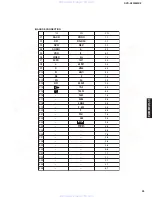
Page 33: ... P15 TRACK 5 3 P16 CHAP 1 4 P17 PAGE 2 4 P18 ANGLE 3 4 P19 D MIX 4 4 P20 P 5 4 P21 PCM 1 5 P22 VSS 2 5 P23 3 5 P24 4 5 P25 5 5 P26 1 6 P27 2 6 P28 3 6 P29 4 6 P30 5 6 P31 1 7 P32 2 7 P33 3 7 P34 4 7 P35 5 7 ANODE CONNECTION www xiaoyu163 com QQ376315150 9 9 2 8 9 4 2 9 8 TEL 13942296513 9 9 2 8 9 4 2 9 8 0 5 1 5 1 3 6 7 3 Q Q TEL 13942296513 QQ 376315150 892498299 TEL 13942296513 QQ 376315150 8924...

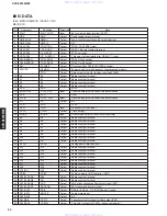
Page 34: ...t H level for current state 26 A4 A4 Output Address output terminal 27 A5 A5 Output Address output terminal 28 A6 A6 Output Address output terminal 29 A7 A7 Output Address output terminal 30 A8 A8 Output Address output terminal 31 A9 A9 Output Address output terminal 32 A10 A10 Output Address output terminal 33 A11 A11 Output Address output terminal 34 AVDD AVDD Analog power terminal 3 3V 35 A12 A...

Page 35: ... ROM rewrite data terminal 74 PULLUP1 TCLK Input Built in ROM rewrite clock terminal 75 NNMI NNMI Input Pulled up by 10KΩ 76 PA0 NIRQ0 IR Input Remote control signal input Not used 77 PA1 NIRQ1 MSREADY Input DSD decoder communication complete signal input terminal 78 PA2 NIRQ2 ADSCIRQ Input ADSC block request signal input 79 PA3 NIRQ3 ODCIRQ Input ODC block request signal input 80 PA4 NIRQ4 MODULE...

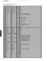
Page 36: ...utput N C 29 RxD2 SCL TA0IN TB5IN RxD2 SCL TA0IN TB5IN Output N C 30 TxD2 SDA TA0OUT TxD2 SDA TA0OUT Output N C 31 TxD1 TxD1 Output Data signal output to RS 232C driver 32 RxD1 RxD1 Input Data signal input from RS 232C driver 33 CLK1 CLK1 Output Data signal output to RS 232C driver 34 CLKS1 CST0 RTS1 CTS1 CLKS1 CST0 RTS1 CTS1 Input Data signal input from RS 232C driver 35 TxD0 TxD0 Output Data sig...

Page 37: ...rection Note 56 A14 A14 Output N C 57 A13 A13 Output N C 58 A12 A12 Output N C 59 A11 A11 Output N C 60 A10 A10 Output N C 61 A9 A9 Output N C 62 Vcc Vcc 3 3v 63 A8 A8 Output N C 64 Vss Vss GND 65 A7 A7 Output N C 66 A6 A6 Output N C 67 A5 A5 Output N C 68 A4 A4 Output N C 69 A3 A3 Output N C 70 A2 A2 Output N C 71 A1 A1 Output N C 72 A0 A0 Output N C 73 D15 INT5 D15 INT5 Output N C 74 D14 INT4 D1...

Page 38: ...L BUS DVD MODULE See page 55 62 and 63 SCHEMATIC DIAGRAM BLOCK DIAGRAM PRINTED CIRCUIT BOARD RS 232C P C B Component side RS 232C P C B Foil side RS 232C REMOTE CONTROL IN OUT 1 30 31 50 51 80 81 100 1 7 14 8 1 1 1 4 8 5 10 20 11 7 14 8 1 5 1 5 MAIN 2 STANDBY LED GND PA2 PA1 PA0 D 3 3 REMOTE MAIN 4 WH BE Power Transformer CS_232C SCK2 GND SO2 SI2 GND SACD Ref No Location D811 D2 D812 D6 D821 C6 IC...

Page 39: ...53 RS 232C P C B See page 55 62 See page 52 MAIN P C B SW810 IC828 IC829 IC830 Q822 IC826 IC823 IC827 w w w x i a o y u 1 6 3 c o m Q Q 3 7 6 3 1 5 1 5 0 9 9 2 8 9 4 2 9 8 T E L 1 3 9 4 2 2 9 6 5 1 3 9 9 2 8 9 4 2 9 8 0 5 1 5 1 3 6 7 3 Q Q TEL 13942296513 QQ 376315150 892498299 TEL 13942296513 QQ 376315150 892498299 http www xiaoyu163 com http www xiaoyu163 com ...
Page 40: ...R DVD_FL DVD_SR DVD_SL DVD_SW DVD_CNT AC3H DACMUT MAGND MAGND DGND SACD_MUTE MODULW_RES EXTRA SW NC 1 16 17 32 1 1 1 1 1 1 1 1 1 5 5 8 1 4 5 8 1 4 5 8 1 4 5 8 1 4 5 5 5 5 8 8 8 8 1 5 8 1 5 8 1 5 8 14 14 14 15 15 28 28 15 28 1 14 15 28 8 9 16 PRINTED CIRCUIT BOARD Ref No Location D304 G6 D305 G5 D306 H2 D307 H3 D308 H4 D309 H4 D310 G3 D311 G3 D312 G4 D313 G5 IC301 F6 IC302 D2 IC303 D3 IC304 D4 IC30...

Page 41: ...7 G5 IC332 G5 Q307 G5 Q308 F5 Q311 F5 Q312 F5 Q313 F5 Q314 G2 Q315 G3 Q316 G3 Q317 G4 Q318 G2 Q319 G2 Q320 G3 Q321 G3 Q322 G4 Q323 G4 Q324 G5 Q325 G4 Q326 G2 Q327 G3 Q328 G4 Q329 G5 Q330 H5 Q331 H6 Q332 H6 Semiconductor Location w w w x i a o y u 1 6 3 c o m Q Q 3 7 6 3 1 5 1 5 0 9 9 2 8 9 4 2 9 8 T E L 1 3 9 4 2 2 9 6 5 1 3 9 9 2 8 9 4 2 9 8 0 5 1 5 1 3 6 7 3 Q Q TEL 13942296513 QQ 376315150 8924...

Page 42: ...3 MIXR MIXL FR FL SR SL SW CNT AC3H DACMUT ADACGND ADACGND DGND SACD_MUTE MODULE_RES EXTRA SW NC 25 AC3 5 AC3 5 D 5 GND STATUS CMD CUSTOM I O SO_S R SCK2 TD0 TD1 SEL_FLASH DSPCLK DGND DGND RCK D 3 3VD TCLK FLASH_RESET P R P B Y COMPONENT 480p 480l VIDEO S VIDEO OPTICAL COAXIAL VIDEO OUT DIGITAL OUT PRINTED CIRCUIT BOARD Ref No Location D606 F3 D607 F3 D609 F2 D610 E2 D613 C2 D614 D2 IC605 C3 IC606...

Page 43: ... B6 IC601 C3 IC603 C3 IC607 D4 IC611 E4 IC612 E6 IC613 F5 Q501 C6 Q502 C6 Q503 B5 Q506 B6 Q602 C3 Q604 C4 Q605 D3 Q606 G4 Q607 F4 Q608 G5 Semiconductor Location w w w x i a o y u 1 6 3 c o m Q Q 3 7 6 3 1 5 1 5 0 9 9 2 8 9 4 2 9 8 T E L 1 3 9 4 2 2 9 6 5 1 3 9 9 2 8 9 4 2 9 8 0 5 1 5 1 3 6 7 3 Q Q TEL 13942296513 QQ 376315150 892498299 TEL 13942296513 QQ 376315150 892498299 http www xiaoyu163 com ...
Page 44: ...LEVEL POWER AC IN PHONES PROGRESSIVE SACD DVD VIDEOOFF VIDEOOFF STANDBY 41 28 37 18 1 2 5 42 42 58 46 65 82 81 78 43 RS 232C GND STANDBY LED REM D 3 3 PA0 PA1 PA2 MAIN 1 L701 PRINTED CIRCUIT BOARD Ref No Location D701 G5 D702 G5 D703 I5 D704 D5 D705 G5 D750 D2 D751 E2 IC750 E3 Semiconductor Location w w w x i a o y u 1 6 3 c o m Q Q 3 7 6 3 1 5 1 5 0 9 9 2 8 9 4 2 9 8 T E L 1 3 9 4 2 2 9 6 5 1 3 9...

Page 45: ... No Location IC701 G6 Q701 E5 Q702 H5 Q703 I6 Q704 D6 Q705 E6 Semiconductor Location w w w x i a o y u 1 6 3 c o m Q Q 3 7 6 3 1 5 1 5 0 9 9 2 8 9 4 2 9 8 T E L 1 3 9 4 2 2 9 6 5 1 3 9 9 2 8 9 4 2 9 8 0 5 1 5 1 3 6 7 3 Q Q TEL 13942296513 QQ 376315150 892498299 TEL 13942296513 QQ 376315150 892498299 http www xiaoyu163 com http www xiaoyu163 com ...

Page 46: ...L BUS DVD MODULE See page 55 62 and 63 SCHEMATIC DIAGRAM BLOCK DIAGRAM PRINTED CIRCUIT BOARD RS 232C P C B Component side RS 232C P C B Foil side RS 232C REMOTE CONTROL IN OUT 1 30 31 50 51 80 81 100 1 7 14 8 1 1 1 4 8 5 10 20 11 7 14 8 1 5 1 5 MAIN 2 STANDBY LED GND PA2 PA1 PA0 D 3 3 REMOTE MAIN 4 WH BE Power Transformer CS_232C SCK2 GND SO2 SI2 GND SACD Ref No Location D811 D2 D812 D6 D821 C6 IC...

Page 47: ...T BOARD MAIN 1 DVD MODULE P C B Foil side w w w x i a o y u 1 6 3 c o m Q Q 3 7 6 3 1 5 1 5 0 9 9 2 8 9 4 2 9 8 T E L 1 3 9 4 2 2 9 6 5 1 3 9 9 2 8 9 4 2 9 8 0 5 1 5 1 3 6 7 3 Q Q TEL 13942296513 QQ 376315150 892498299 TEL 13942296513 QQ 376315150 892498299 http www xiaoyu163 com http www xiaoyu163 com ...

Page 48: ... SO2 DGND REM D 3 3VD PA2 FL_RESET VOFF_LED PROG_LED DVD_LED LED_SACD PA0 PA1 STATUS CMD IR SO_S R SCK2 TCLK TD1 SEL_FLASH DSPCLK DGND DGND RCK D 3 3VD TD0 FLASH_RESET A 5 AGND D 5S DGND 2 5S DGND SGND M 9 1 1 1 8 16 9 1 1 1 7 8 14 1 1 8 16 9 1 1 1 7 1 1 44 45 88 89 132 133 176 1 25 26 50 51 75 76 100 7 16 8 1 1 4 8 5 7 16 8 8 14 1 4 5 8 4 5 8 4 5 8 8 16 9 7 8 14 16 17 32 33 48 49 64 8 16 9 4 5 5 ...

Page 49: ... IC504 TS7ST00F 2 Input NAND Gate 1 2 3 IN B IN A GND 4 5 VCC OUT Y IC505 TC7WU04F Triple Inverter 1A 3Y GND VCC 1Y 1 2 3 4 5 2A 3A 2Y 6 7 8 13 12 14 G ACK SER D G D G R D G D G R D G D G R D G D G R D G D G R D G D G R D G D G R D G D G R 11 10 SCK SECR 9 7 6 5 4 3 2 1 15 QA QB QC QD QE QF QG QH QM SERIAL DATA OUTPUT PARALLEL DATA OUTPUTS IC612 74VHC595SJX 8 Bit Shift Register IC613 TC7S32F 2 Inp...

Page 50: ...ge 48 to SACD N8 Page 49 to AUDIO 1 F10 Page 49 to AUDIO 2 B10 MAIN 1 MAIN 4 MAIN 5 Page 53 to RS 232C I2 Page 53 to RS 232C I2 Page 53 to RS 232C K2 RESET SIGNAL GENERATOR BUFFER RESET SIGNAL GENERATOR REGULATOR REGULATOR POWER SW REGULATOR REGULATOR REGULATOR REGULATOR POWER SW 2 6 3 1 3 1 3 1 3 1 5 0 5 8 5 8 5 8 4 9 4 9 9 0 7 0 7 0 4 9 0 0 0 0 14 0 14 0 14 0 14 0 14 0 14 0 1 1 2 4 0 0 0 0 0 0 0...

Page 51: ...rcuit DIG00 63 53 DIG10 IC701 M66003 0101FP FL Display Driver 2 data timing clock dot data write scan pulse IC750 µPC4570HA Dual OP Amp Vcc Vo1 Vm1 Vm1 VEE Vm2 Vm2 Vo2 Vcc 1 2 3 4 5 6 7 8 9 1 2 Page 51 to MAIN 1 D10 Page 48 to SACD J10 Page 53 to RS 232C E10 Page 51 to MAIN 1 A6 1 4 3 2 8 5 6 7 FL DRIVER FL DISPLAY IR REMOTE HEADPHONE AMP PHONES LEVEL PRGR LED DRIVER VOFF LED DRIVER DVD LED DRIVER...

Page 52: ...DVD MODULE 1 8 FEP SECTION w w w x i a o y u 1 6 3 c o m Q Q 3 7 6 3 1 5 1 5 0 9 9 2 8 9 4 2 9 8 T E L 1 3 9 4 2 2 9 6 5 1 3 9 9 2 8 9 4 2 9 8 0 5 1 5 1 3 6 7 3 Q Q TEL 13942296513 QQ 376315150 892498299 TEL 13942296513 QQ 376315150 892498299 http www xiaoyu163 com http www xiaoyu163 com ...

Page 53: ... 8 SODC DRV SECTION w w w x i a o y u 1 6 3 c o m Q Q 3 7 6 3 1 5 1 5 0 9 9 2 8 9 4 2 9 8 T E L 1 3 9 4 2 2 9 6 5 1 3 9 9 2 8 9 4 2 9 8 0 5 1 5 1 3 6 7 3 Q Q TEL 13942296513 QQ 376315150 892498299 TEL 13942296513 QQ 376315150 892498299 http www xiaoyu163 com http www xiaoyu163 com ...

Page 54: ... 3 8 AVDEC SECTION w w w x i a o y u 1 6 3 c o m Q Q 3 7 6 3 1 5 1 5 0 9 9 2 8 9 4 2 9 8 T E L 1 3 9 4 2 2 9 6 5 1 3 9 9 2 8 9 4 2 9 8 0 5 1 5 1 3 6 7 3 Q Q TEL 13942296513 QQ 376315150 892498299 TEL 13942296513 QQ 376315150 892498299 http www xiaoyu163 com http www xiaoyu163 com ...

Page 55: ...8 PROGRESSIVE SECTION w w w x i a o y u 1 6 3 c o m Q Q 3 7 6 3 1 5 1 5 0 9 9 2 8 9 4 2 9 8 T E L 1 3 9 4 2 2 9 6 5 1 3 9 9 2 8 9 4 2 9 8 0 5 1 5 1 3 6 7 3 Q Q TEL 13942296513 QQ 376315150 892498299 TEL 13942296513 QQ 376315150 892498299 http www xiaoyu163 com http www xiaoyu163 com ...
Page 56: ...D MODULE 5 8 VIDEO DAC SECTION w w w x i a o y u 1 6 3 c o m Q Q 3 7 6 3 1 5 1 5 0 9 9 2 8 9 4 2 9 8 T E L 1 3 9 4 2 2 9 6 5 1 3 9 9 2 8 9 4 2 9 8 0 5 1 5 1 3 6 7 3 Q Q TEL 13942296513 QQ 376315150 892498299 TEL 13942296513 QQ 376315150 892498299 http www xiaoyu163 com http www xiaoyu163 com ...

Page 57: ...D MODULE 6 8 AUDIO DAC SECTION w w w x i a o y u 1 6 3 c o m Q Q 3 7 6 3 1 5 1 5 0 9 9 2 8 9 4 2 9 8 T E L 1 3 9 4 2 2 9 6 5 1 3 9 9 2 8 9 4 2 9 8 0 5 1 5 1 3 6 7 3 Q Q TEL 13942296513 QQ 376315150 892498299 TEL 13942296513 QQ 376315150 892498299 http www xiaoyu163 com http www xiaoyu163 com ...

Page 58: ...VD MODULE 7 8 WM SECTION w w w x i a o y u 1 6 3 c o m Q Q 3 7 6 3 1 5 1 5 0 9 9 2 8 9 4 2 9 8 T E L 1 3 9 4 2 2 9 6 5 1 3 9 9 2 8 9 4 2 9 8 0 5 1 5 1 3 6 7 3 Q Q TEL 13942296513 QQ 376315150 892498299 TEL 13942296513 QQ 376315150 892498299 http www xiaoyu163 com http www xiaoyu163 com ...
Page 59: ...AGRAM DVD MODULE 8 8 CPU SECTION w w w x i a o y u 1 6 3 c o m Q Q 3 7 6 3 1 5 1 5 0 9 9 2 8 9 4 2 9 8 T E L 1 3 9 4 2 2 9 6 5 1 3 9 9 2 8 9 4 2 9 8 0 5 1 5 1 3 6 7 3 Q Q TEL 13942296513 QQ 376315150 892498299 TEL 13942296513 QQ 376315150 892498299 http www xiaoyu163 com http www xiaoyu163 com ...
Page 60: ...ACD A3 SCHEMATIC DIAGRAM TERMINAL P C B www xiaoyu163 com QQ376315150 9 9 2 8 9 4 2 9 8 TEL 13942296513 9 9 2 8 9 4 2 9 8 0 5 1 5 1 3 6 7 3 Q Q TEL 13942296513 QQ 376315150 892498299 TEL 13942296513 QQ 376315150 892498299 http www xiaoyu163 com http www xiaoyu163 com ...
Page 61: ...TPUTS 17 T1OUT 12 T2IN 8 T2OUT 15 R1OUT TTL CMOS OUTPUTS RS 232 INPUTS 16 R1IN 10 R2OUT 9 R2IN 1 25V R1 R2 2 1 6 GND COUNTER OSC SUPPLY VOLTAGE OUTPUT L RESET TYPE Page 51 to MAIN 4 to Power Transformer to Power Transformer L5 Page 51 K8 Page 51 J5 Page 48 to SACD F10 Page 52 to MAIN 2 A5 RS 232C REMOTE CONTROL RS 232C DRIVER PHOTO COUPLER SUB CPU AND REGULATOR BOTTOM HOLD RELAY DRIVER REGULATOR R...

Page 62: ... 3 4 7 2 6 1 12 13 11 9 10 8 5 4 6 5 4 3 1 2 10 12 13 9 7 14 6 4 5 2 1 3 14 7 5 1 3 9 11 13 2 4 5 1 4 2 3 8 1 7 4 5 6 2 3 IC32 TC7WH74FU D type Flip Flop with Preset and Clear 7 S 1 C PR 6 R CLR 2 D D CK 5 3 Q Q 4 8 5 2 3 6 7 1 3 5 4 2 IC48 74LCX07MTCX Hex Buffer A0 O0 O1 VCC A3 1 2 3 4 11 A1 O3 A4 12 13 14 A2 O2 O4 A5 5 6 7 O5 8 9 10 GND Point C Pin 4 of IC41 and Collector of Q14 Power ON Connect...

Page 63: ... 5 6 2 4 3 1 0 7 8 5 4 6 3 1 2 8 7 REGULATOR TRACKING REGULATOR RESET SIGNAL GENERATOR POWER ON MUTE DRIVER MUTE DRIVER SW GAIN CONTROL 24K 24K 12K 12K 1K 47 47 50 47 50 47 50 47 50 5600P 100 5600P 100 2 5 2 6 5 0 2 5 2 5 2 5 2 5 2 4 2 4 2 4 2 4 5 0 2 4 2 4 3 1 0 0 0 0 3 3 3 3 2 5 5 0 5 0 5 0 0 0 0 2 5 5 0 0 0 5 0 2 5 2 5 2 5 2 5 2 4 2 4 2 4 2 4 5 0 2 4 2 4 3 1 0 0 0 0 3 3 3 3 2 5 5 0 5 0 5 0 0 0 ...

Reviews: