DVD-S510/DV-S5350
18
■
TEST INSTRUCTIONS DISPLAY BOARD
1. Display board
1.1 Introduction
These test instructions are written for all versions of the
display PCB.
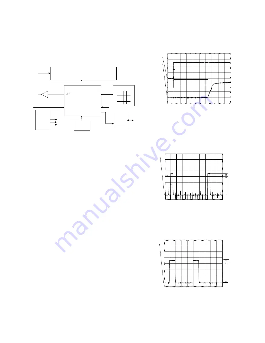
The contents of the PCB can be split up into next blocks:
Processor
slave up
I2C
Display
Key-matrix
RC-Eye
V filament
V filament
Buffer
P50
I/O
Supply:
+5Vstby
+12V
-40V
Figure 1
1.2 Functionality description:
The essential component of the display PCB is the
µ
P
(slave).
This slave works on an 8MHz resonator and has a reset
circuit that is triggered by the +5Vstby. After the reset
pulse, the standby control line will release the reset of the
host
µ
P. This host
µ
P will then initialize the slave. In
addition, when going to stand-by, the slave will put the
host
µ
P in reset. When the slave receives the right IR or
key code to leave the standby mode, the reset of the host
µ
P will be released.
Other slave functions are:
• Square signal generator to generate the filament
voltage, which is required for an AC FTD.
• Generating the grid and segment scanning for the FTD.
• Generating a scanning grid for the keys (separated
from display scanning).
• Having inputs for RC (RC5 and RC6) and P50 (P50
controller is built in).
1.3 Reset
Check next reset timing with an oscilloscope at pin 10 of
the microprocessor.
PM3392A
ch1
ch2
CH1 2.00 V=
CH2 2 V= BWL MTB 100ms- 1.04dv ch2+
1
2
T
T1
Figure 2
Timing: 400msec < T1 > 700msec.
CH1: +5Vstby voltage at power on.
CH2: Voltage at pin 10.
1.4 Display steering
Check next timing and level for all grid-lines (G1 r G14).
PM3392A
ch1
ch1: low =-34.2 V
ch1: high= 3.98 V
STOP
CH1 10.0 V= MTB 200us 2324us ch1+
1
T
A
B
Figure 3
1. Check level A: +4V5 +/-10% for grid lines 1 => 11
2. Check level A: +4V0 +/-10% for grid lines 12 => 14
3. Check level B: -33V +/-10%
4. Check timing and levels of segment-lines P1 => P10:
PM3392A
ch1
CH1 10.0 V= BWL MTB 500us- 1.04dv ch1+
1
T
A
B
Figure 4
Level A:+4V5 +/-10%
Level B:-33V +/-10%
The data on these segment lines depend on the
characters that are displayed.
The characters can be set by sending I2C commands to
the display.
See the Slave URS how to send a display command.
Summary of Contents for DVD-S510
Page 5: ...DVD S510 DV S5350 4 FRONT PANELS DVD S510 DV S5350 REMOTE CONTROL TRANSMITTER...
Page 47: ...A B C D E F G H I J 1 2 3 4 5 6 7 DVD S510 DV S5350 53 52 PRINTED CIRCUIT BOARD MONO Top view...
Page 50: ...A B C D E F G H I J 1 2 3 4 5 7 DVD S510 DV S5350 6 59 58 PRINTED CIRCUIT BOARD A V U C A R T...
Page 51: ...A B C D E F G H I J 1 2 3 4 5 6 7 DVD S510 DV S5350 _Z _A 61 60 PRINTED CIRCUIT BOARD A V B G...
Page 52: ...A B C D E F G H I J 1 2 3 4 5 7 DVD S510 DV S5350 6 63 62 PRINTED CIRCUIT BOARD DISPLAY...
Page 53: ...A B C D E F G H I J 1 2 3 4 5 6 7 DVD S510 DV S5350 65 64 PRINTED CIRCUIT BOARD POWER B G...


