DVD-S795/S705
2 - 13
14.
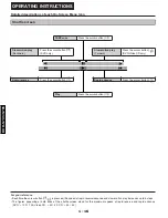
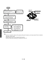
Optical Pickup Tilt Adjustment
Main unit
service display
Tangential adjustment screw
Tilt adjustment screw
T1 (inner periphery) play
T2 (outer periphery) play
Measurement point
Adjustment point
Mode
Disc
Measuring equipment, tools
Adjustment value
Hex wrench (part number: TX946380)
Screw lock (part number: TX946400)
Adjust to the minimum jitter value.
DVDT-S15 (AAX07320)
or
DVDT-S01 (TX946080)
Tangential adjustment screw
Tilt adjustment screw 1
Tilt adjustment screw 2
Change in
jitter value
A
B
Optimum
point
Adjustment angle
•
Jitter value depends on the model:
(1) If the jitter value changes like A,
the optimum point is easy to find
(2) If the jitter value changes like A,
set the optimum point near the middle.
STEP1
STEP2
STEP3
STEP4
STEP5
STEP6
NG
OK
"STOP/PAUSE" button: main unit
"OPEN/CLOSE" button: main unit
"5" button: remote control unit
Press
simultaneously
Main unit display
Check to see that "JIT xxx" is displayed.
Present jitter value.
Play test disc title 1
(inner periphery)
Tangential adjustment screw
Adjust to the minimum jitter value.
Do steps 3-5
from the bottom
of the main unit
using a hex wrench.
•
Replaced the optical pickup.
•
Replaced the spindle motor.
•
Replaced the peripheral parts
of the optical pickup, etc.
Play the disc to make sure
there is no picture
degradration in the inner,
middle and outer
peripheries, and no audio
skipping.
Play test disc title 43
(outer periphery)
Tilt adjustment screw 1
Adjust to the minimum jitter value.
Play test disc title 43
(outer periphery)
Tilt adjustment screw 2
Adjust to the minimum jitter value.
Check condition
after adjustment
Repeat adjustment tilt
adjustment screws
1 and 2 alternately,
two or three times.
STEP7
STEP7
Summary of Contents for DVD-S795
Page 7: ...DVD S795 S705 1 5 REAR PANELS U C models DVD S795 S705 B G models G model Gold A model...
Page 39: ...3 3 3 4 BLOCK DIAGRAM 1 OVERALL BLOCK DIAGRAM...
Page 40: ...3 5 2 SERVO BLOCK DIAGRAM 3 6...
Page 41: ...3 7 3 VIDEO BLOCK DIAGRAM 3 8...
Page 42: ...3 9 4 AUDIO BLOCK DIAGRAM 3 10...
Page 60: ...9 0 0 0 0 0 8 9 0 0 3 45 18 FRONT SW HEAD PHONE POWER SW SCHEMATIC DIAGRAM 3 46...


