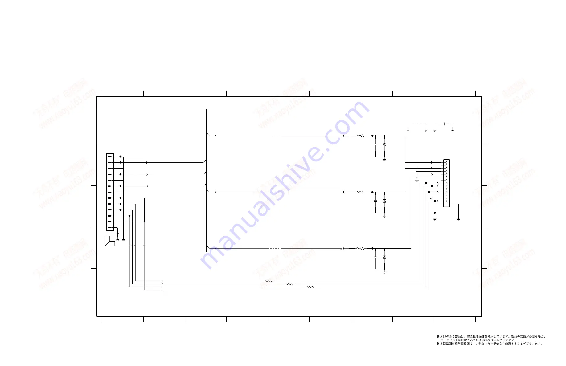
DVR-S300/
NX-P301/NX-P302
55
*
*
*
*
*
*
1101 B1
1102 B9
2110 A6
2111 C6
2112 D6
2116 B7
2117 C7
2118 D7
2119 A8
2120 A9
3122 A7
3123 C7
3124 D7
3125 E4
3126 E5
3127 E5
4109 A8
4111 A5
4112 B5
4113 C5
6101 B7
6102 C7
6103 D7
F101 B1
F102 B1
F103 B1
F104 B1
F105 C1
F106 C1
F107 C1
F108 C1
F109 D1
F110 C2
F111 A7
F112 C7
F113 D7
F114 B8
F115 C8
F116 C8
F117 C8
F118 C9
1
2
3
4
5
6
Gnd
Line 3
Line 2
Line 1
AV1
7
8
9
1
2
3
4
5
6
7
8
9
A
B
C
A
B
C
D
E
Pb
4V
Pb
Gnd
* Option
Y
4V
4V
Pr
Gnd
PlugDet
PlugDet Gnd
Y
Reserved 2
Pr
Reserved 1
Reserved 3
6103
BZX384-C4V7
F111
2112
470u
AV
F102
7
8
9
10
11
12
13
14
2
3
4
5
6
CSS0514-0801
1102
1
C
75R
3123
BZX384-C4V7
6102
100p
2117
470u
2111
10K
3127
3126
10K
10K
3125
2110
470u
1
10
11
12
13
2
3
4
5
6
7
8
9
1101
FMN
4113
4111
4112
F117
AV
AV
F118
C
2120
100n
F116
C
2118
100p
4109
F106
F107
F105
F104
6101
BZX384-C4V7
F114
F115
F103
3122
75R
C
F109
C
C
F101
F108
C
F113
2116
100p
75R
3124
F112
V
U
Y
PLUGDETN
Y
U
V
LINE_2
LINE_1
LINE_3
モニター出力
D1/D2
HDMI D2 BOARD
(J model)
E
13
T
O
1704 OF A
V
BO
ARD
P
age 50
★
Components having special characteristics are marked
s
and must be replaced
with parts having specifications equal to those originally installed.
★
Schematic diagram is subject to change without notice.
The first digit of a component indicates the component type.
1xxx : Connector
3xxx : Resistor
5xxx : Coil
7xxx : IC, Transistor, FET
2xxx : Capacitor
4xxx : SMD jumper
6xxx : Diode
9xxx : Wire jumper
■
DVR-S300 SCHEMATIC DIAGRAM
FOR INFORMATION ONLY (NO REPLACEMENT COMPONENT PARTS WILL BE AVAILABLE)
w w w . x i a o y u 1 6 3 . c o m
Q Q 3 7 6 3 1 5 1 5 0
9
9
2
8
9
4
2
9
8
T E L
1 3 9 4 2 2 9 6 5 1 3
9
9
2
8
9
4
2
9
8
0
5
1
5
1
3
6
7
3
Q
Q
TEL 13942296513 QQ 376315150 892498299
TEL 13942296513 QQ 376315150 892498299


