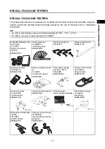
BASIC SERVICE INFORMATION
1-4
1
2
3
4
5
6
7
8
9
10
GENER
A
L IN
FORMA
T
ION
BASIC SERVICE INFORMATION
ELECTRICAL SYSTEM
Checking the electrical system
TIP
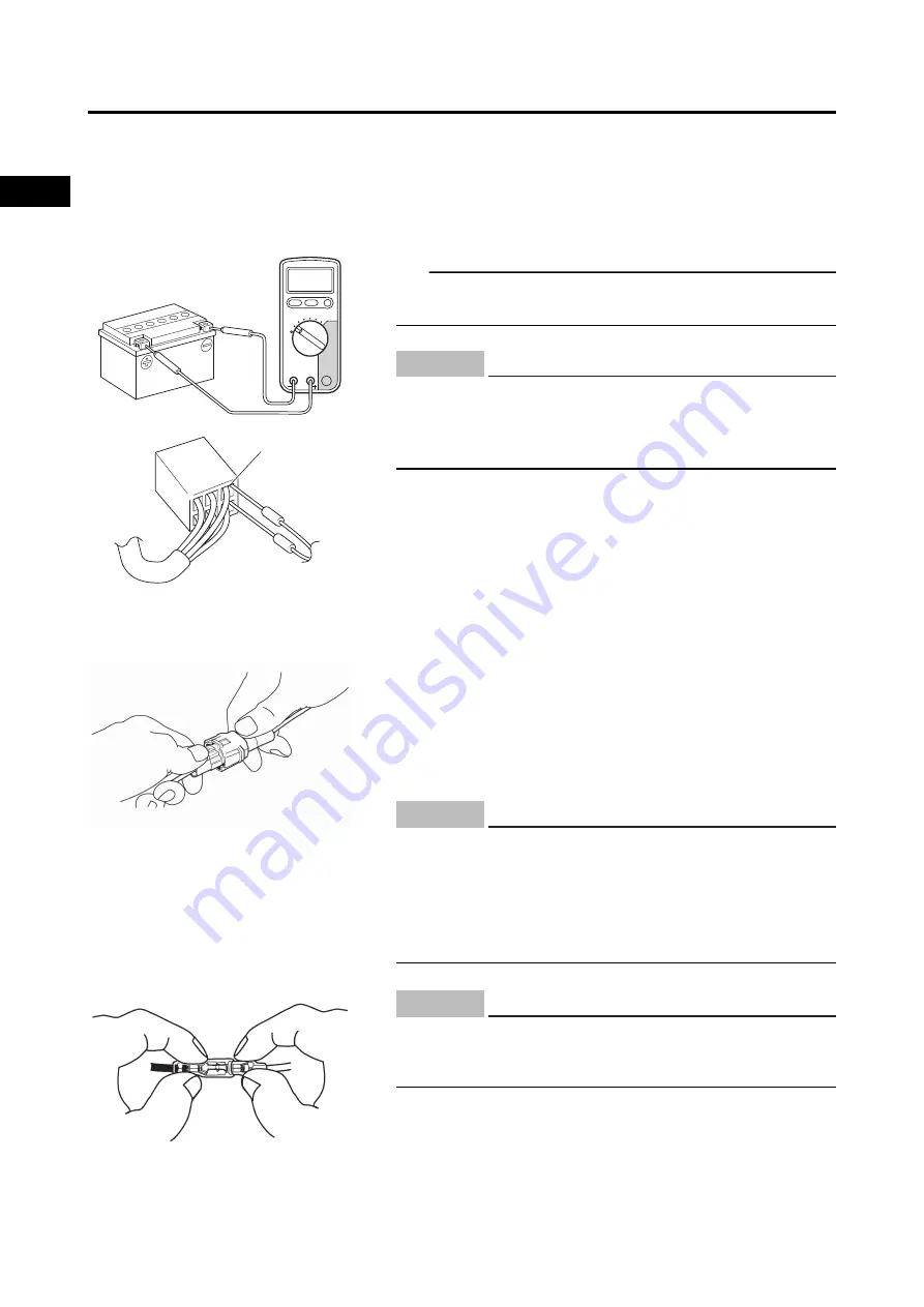
Before checking the electrical system, make sure that the
battery voltage is at least 12 V.
Checking the connections
Check the leads, couplers, and connectors for stains, rust,
moisture, etc.
1.
Disconnect:
• Lead
• Coupler
• Connector
a
Never insert the tester probes into the coupler termi-
nal slots. Always insert the probes from the opposite
end “a” of the coupler, taking care not to loosen or
damage the leads.
NOTICE
• When disconnecting a coupler, release the coupler
lock, hold both sections of the coupler securely, and
then disconnect the coupler.
• There are many types of coupler locks; therefore, be
sure to check the type of coupler lock before discon-
necting the coupler.
NOTICE
When disconnecting a connector, do not pull the
leads. Hold both sections of the connector securely,
and then disconnect the connector.
NOTICE
Summary of Contents for EF2200iS
Page 2: ...7PC F8197 E0_Hyoshi indd 3 4 2019 08 28 16 31 47 ...
Page 18: ...SPECIAL TOOLS AND TESTERS 1 8 1 2 3 4 5 6 7 8 9 10 GENERAL INFORMATION MEMO ...
Page 50: ...PERIODIC MAINTENANCE 2 32 1 2 3 4 5 6 7 8 9 10 PERIODIC CHECKS AND ADJUSTMENTS MEMO ...
Page 99: ...FUEL PUMP 4 7 1 2 3 4 5 6 7 8 9 10 CARBURETOR MEMO ...
Page 116: ...ELECTRICAL COMPONENTS 5 17 1 2 3 4 5 6 7 8 9 10 ELECTRICAL MEMO ...
Page 138: ...WIRE ROUTING DIAGRAM 7 16 1 2 3 4 5 6 7 8 9 10 SPECIFICATIONS ENGINE AND GENERATOR ...
Page 140: ...WIRE ROUTING DIAGRAM 7 18 1 2 3 4 5 6 7 8 9 10 SPECIFICATIONS UPPER SIDE AND LEFT SIDE VIEW ...
Page 142: ...WIRE ROUTING DIAGRAM 7 20 1 2 3 4 5 6 7 8 9 10 SPECIFICATIONS CONTROL UNIT ...
Page 144: ...WIRE ROUTING DIAGRAM 7 22 1 2 3 4 5 6 7 8 9 10 SPECIFICATIONS GENERATOR ...
Page 148: ...WIRE ROUTING DIAGRAM 7 26 1 2 3 4 5 6 7 8 9 10 SPECIFICATIONS CARBURETOR AND AIR FILTER ...
Page 150: ...WIRE ROUTING DIAGRAM 7 28 1 2 3 4 5 6 7 8 9 10 SPECIFICATIONS FUEL TANK AND FUEL HOSES ...
Page 152: ...WIRE ROUTING DIAGRAM 7 30 1 2 3 4 5 6 7 8 9 10 SPECIFICATIONS ...
Page 160: ...MEMO ...
Page 161: ...7PC F8197 E0_Hyoshi indd 3 4 2019 08 28 16 31 47 ...


