background image

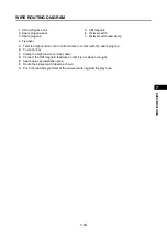
WIRE ROUTING DIAGRAM

7-24

1

2

3

4

5

6

7

8

9

10

SP

ECIFIC

A

T

IO

NS

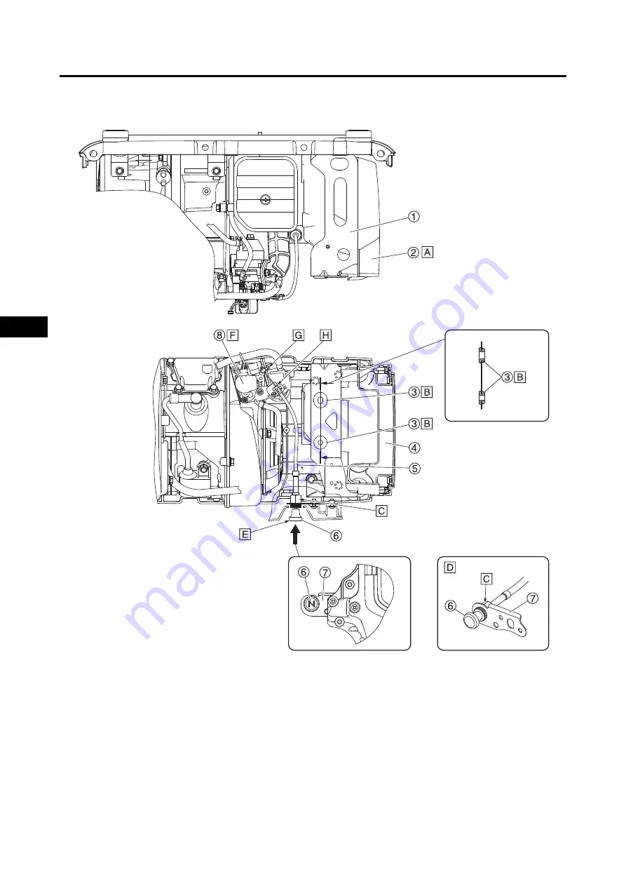
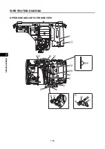
UPPER SIDE AND AIR FILTER SIDE VIEW

Summary of Contents for EF2200iS

Page 1: ...SERVICE MANUAL EF2200iS 7PC F8197 E0 2019 09 1 E 7PC F8197 E0_Hyoshi indd 1 2 2019 08 28 16 31 47 ...

Page 2: ...7PC F8197 E0_Hyoshi indd 3 4 2019 08 28 16 31 47 ...

Page 3: ...NUAL 2019 by Yamaha Motor Powered Products Co Ltd 1st Edition July 2019 All rights reserved Any reprinting or unauthorized use without the written permission of Yamaha Motor Powered Products Co Ltd is expressly prohibited ...

Page 4: ...ations and significant changes in specifications or procedures will be forwarded to all authorized Yamaha dealers and will appear in future editions of this manual where applicable TIP Designs and specifications are subject to change without notice IMPORTANT MANUAL INFORMATION Particularly important information is distinguished in this manual by the following notations This is the safety alert sym...

Page 5: ...han the section title 2 To help identify parts and clarify procedure steps there are exploded diagrams at the start of each removal and disassembly section 3 Numbers are given in the order of the jobs in the exploded diagram A number indicates a disas sembly step 4 Symbols indicate parts to be lubricated or replaced 5 Refer to SYMBOLS A job instruction chart accompanies the exploded diagram provid...

Page 6: ...t relevant to every generator SYMBOL DEFINITION SYMBOL DEFINITION Filling fluid Lubricant Special tool Tightening torque Wear limit clearance Engine speed Electrical data Replace the part with a new one Lithium soap base grease Molybdenum disulfide grease Engine oil Apply locking agent LOCTITE T R New LS M E LT ...

Page 7: ...GENERAL INFORMATION PERIODIC CHECKS AND ADJUSTMENTS ENGINE CARBURETOR ELECTRICAL TROUBLESHOOTING SPECIFICATIONS 1 2 3 4 5 6 7 8 9 10 INDEX ...

Page 8: ...NE OIL LEAKAGE 2 10 ENGINE OIL LEVEL 2 11 REPLACING THE ENGINE OIL 2 12 FUEL LEAKAGE 2 13 FUEL HOSE 2 13 SPARK PLUG 2 14 AIR FILTER ELEMENT 2 15 MUFFLER 2 16 FUEL TANK STRAINER 2 17 FUEL COCK STRAINER 2 18 BREATHER HOSE 2 20 CYLINDER HEAD DECARBONIZATION 2 20 ADJUSTING THE VALVE CLEARANCE 2 21 MEASURING THE COMPRESSION PRESSURE 2 23 RATED ENGINE SPEED 2 25 RECOIL STARTER 2 25 OUTER COVERS 2 25 FIT...

Page 9: ...G ROD CRANKSHAFT AND CRANKCASE 3 33 CHECKING THE CYLINDER AND PISTON 3 35 CHECKING THE CRANKCASE 3 36 CHECKING THE PISTON PIN 3 36 CHECKING THE PISTON RINGS 3 37 CHECKING THE CRANKSHAFT 3 39 CHECKING THE CONNECTING ROD OIL CLEARANCE 3 39 INSTALLING THE PISTON AND PISTON RINGS 3 40 INSTALLING THE CRANKSHAFT 3 41 CARBURETOR REMOVING THE CARBURETOR AND AIR FILTER 4 1 DISASSEMBLING THE CARBURETOR 4 2 ...

Page 10: ...ED IS UNEVEN 6 6 SPECIFICATIONS GENERAL SPECIFICATIONS 7 1 MAINTENANCE SPECIFICATIONS 7 4 ENGINE 7 4 ELECTRICAL 7 7 GENERATOR 7 7 TIGHTENING TORQUES 7 8 GENERAL TORQUE SPECIFICATIONS 7 10 LUBRICATION POINTS AND TYPE OF LUBRICANTS 7 11 WIRE ROUTING DIAGRAM 7 12 CONTROL PANEL AND CONTROL BOX FOR EUROPE AND KOREA 7 12 CONTROL PANEL AND CONTROL BOX FOR AUSTRALIA AND CHINA 7 14 ENGINE AND GENERATOR 7 1...

Page 11: ...esigns and specifications are subject to change without notice STARTING SERIAL NUMBER IMPORTANT INFORMATION PREPARATION FOR REMOVAL AND DISASSEMBLY CAUTION ON SERVICE Fire prevention When servicing the engine always keep the engine and yourself away from fire NOTES ON SERVICE Correct tools Be sure to use the correct special tool for the job to guard against damage 3 3 1 Code Starting serial number...

Page 12: ... O rings cotter pins and cir clips with new parts when servicing engine Tightening torque Be sure to follow torque specifications When tightening bolts nuts or screws start with the largest diameter fas tener and work from an inner position to an outer position in a crisscross pattern Notes on disassembly and assembly Parts should be cleaned in solvent and blown dry with compressed air after disas...

Page 13: ...ld be replaced when an engine is overhauled All gaskets surfaces oil seal lips and O rings must be cleaned 2 Properly oil all mating parts and bearings during reas sembly Apply grease to the oil seal lips BEARINGS AND OIL SEALS Install the bearing s 1 and oil seal s 2 with their manu facture s marks or numbers facing outward In other words the stamped letters must be on the side exposed to view Wh...

Page 14: ...er insert the tester probes into the coupler termi nal slots Always insert the probes from the opposite end a of the coupler taking care not to loosen or damage the leads NOTICE When disconnecting a coupler release the coupler lock hold both sections of the coupler securely and then disconnect the coupler There are many types of coupler locks therefore be sure to check the type of coupler lock bef...

Page 15: ...s Loose connection Connect properly TIP If the pin 1 on the terminal is flattened bend it up After disassembling and assembling a coupler pull on the leads to make sure that they are installed securely 4 Connect Lead Coupler Connector TIP When connecting a coupler or connector push both sec tions of the coupler or connector together until they are connected securely Make sure all connections are t...

Page 16: ... and coupler of the TCI unit CDI unit when replacing the TCI unit CDI unit As a quick remedy use a contact revitalizer available at most part stores Model 88 Multimeter with tachometer YU A1927 Digital circuit tester CD732 90890 03243 For waterproof couplers never insert the tester leads directly into the coupler When performing any checks using a waterproof coupler use the specified test har ness...

Page 17: ... gauge set YU 26900 9 Thickness gauge 90890 03268 Six piece tappet set YM A5970 Tappet adjusting tool 90890 01311 Digital tachometer YU 39951 B 90890 06760 Engine compression tes ter YU 33223 Compression gauge 90890 03081 Compression gauge extension 73mm YM 04082 90890 04082 Primary clutch holder YS 01880 A Sheave holder 90890 01701 Heavy duty puller YU 33270 B Flywheel puller 90890 01362 Valve sp...

Page 18: ...SPECIAL TOOLS AND TESTERS 1 8 1 2 3 4 5 6 7 8 9 10 GENERAL INFORMATION MEMO ...

Page 19: ...life The need for costly overhaul work will be greatly reduced This information applies to machines already in service as well as new machines that are being prepared for sale All service technicians should be familiar with this entire chapter MAINTENANCE INTERVALS CHART Proper periodic maintenance is important Especially important are the maintenance services related to emissions control These co...

Page 20: ...akage Fuel hose Visual inspection Check for cracks or damage with fin gers Spark plug Clean and replace if necessary Air filter Check for cracks or damage Clean 2 Muffler screen Check condition Fuel tank strainer Check for dirt and clogging Clean if necessary Check for cracks Fuel cock strainer Remove the cock check for clogging and clean if necessary Breather hose Check for poor connection Cylind...

Page 21: ...he parts in the order listed 1 Rear cover 1 1 2 Cap 1 3 Side cover right 1 4 Side cover left 1 5 Fuel tank cap 1 6 Holder 1 7 Access cap 1 8 Rear cover 2 1 9 Carburetor fuel drain cock 1 10 Washer 6 1 2 3 4 5 6 7 8 9 10 7 N m 0 7 kgf m 5 2 lb ft 1 8 N m 0 18 kgf m 1 3 lb ft 1 8 N m 0 18 kgf m 1 3 lb ft 1 5 N m 0 15 kgf m 1 1 lb ft 7 N m 0 7 kgf m 5 2 lb ft 7 N m 0 7 kgf m 5 2 lb ft 1 8 N m 0 18 kg...

Page 22: ...move the parts in the order listed 1 Rear cover 1 1 2 Cap 1 3 Side cover right 1 4 Side cover left 1 5 Fuel tank cap 1 6 Holder 1 7 Access cap 1 8 Rear cover 2 1 9 Carburetor fuel drain cock 1 1 2 3 4 5 6 7 8 9 1 8 N m 0 18 kgf m 1 3 lb ft 1 8 N m 0 18 kgf m 1 3 lb ft 1 8 N m 0 18 kgf m 1 3 lb ft 0 8 N m 0 08 kgf m 0 59 lb ft 7 N m 0 7 kgf m 5 2 lb ft 7 N m 0 7 kgf m 5 2 lb ft 7 N m 0 7 kgf m 5 2 ...

Page 23: ...K TIP It is recommended to remove the rear cover 2 and the fuel tank together without disassembling The rear cover 2 is hard to detach from the fuel tank Order Job Parts to remove Q ty Remarks Removing the rear cover 2 and fuel tank Remove the parts in the order listed 1 Rear cover 2 1 2 Fuel tank 1 2 1 ...

Page 24: ... in the order listed 1 Recoil starter handle 1 2 Front cover 1 1 3 Choke cable holder 1 4 Fuel hose 3 5 Pulsar hose 1 6 Ground Earth lead 1 7 Engine switch together with fuel cock 1 8 Front cover 2 1 9 Fuel tank 1 10 Fuel tank strainer 1 11 Washer 2 For Europe 1 2 3 4 4 4 5 6 7 8 9 10 1 8 N m 0 18 kgf m 1 3 lb ft 7 N m 0 7 kgf m 5 2 lb ft 1 8 N m 0 18 kgf m 1 3 lb ft 2 5 N m 0 25 kgf m 1 8 lb ft 1...

Page 25: ...CKS AND ADJUSTMENTS TIP When removing covers it is easier to work if you take into consideration the following points as nec essary 1 Loosen the clamp 2 Remove the clamp 3 Disconnect the 2 pin coupler 4 Remove the clamp 5 Remove the ground earth lead 2 1 3 4 5 ...

Page 26: ...ng the rear cover 2 as it is difficult to re insert the drain hose into the hole of the rear cover 2 3 Remove Recoil starter handle 1 TIP Tie a knot a in the starter rope 2 in front of the recoil starter handle 1 to prevent the starter rope from entering the starter case and then untie the knot b on the starter handle side to remove 4 Remove Choke cable holder 1 Screw 2 5 Drain the fuel from the f...

Page 27: ...t straight out 9 Remove Fuel hose Fuel tank INSTALLING THE COVERS AND FUEL TANK 1 Install Fuel tank 1 Fuel hose TIP When you install the fuel tank securely engage the projec tion of fuel tank with the grommet of fuel tank bracket 2 2 Install Front cover 2 Front cover 1 TIP Place the projection a of fuel tank 2 into the groove b at the rear of front cover 2 1 and install them 1 2 3 Take care not to...

Page 28: ... starter rope into the starter handle and install it inside of the starter handle 5 Install Rear cover 2 1 TIP Insert the projection a of fuel tank 2 into the groove b at the rear of rear cover 2 1 and install them 6 Install Fuel tank cap Side cover right Side cover left Rear cover 1 PERIODIC MAINTENANCE ENGINE OIL LEAKAGE 1 Place the generator on a level surface 2 Check the areas outside of the e...

Page 29: ...tch to I RUN c Pull the recoil starter handle d Check that the oil level warning light flashes Oil level warning light flashes Add oil 2 Remove Rear cover 1 Refer to COVERS AND FUEL TANK on page 2 3 Oil filler cap 1 3 Check Check that the engine oil is at the specified level a Place the generator on a level surface b Warm up the engine for several minutes c Turn the engine switch to STOP 1 1 ...

Page 30: ... AND FUEL TANK on page 2 3 REPLACING THE ENGINE OIL 1 Warm up the engine for several minutes and then stop the engine 2 Remove Rear cover 1 Refer to COVERS AND FUEL TANK on page 2 3 Oil filler cap 1 O ring 2 3 Place an oil pan under the generator Tilt the genera tor to drain the oil completely 4 Fill Engine oil Make sure to fill with the recommended engine oil from the oil filler hole in the crank...

Page 31: ...S AND FUEL TANK on page 2 3 2 Check Leakage Check at fuel tank engine switch together with fuel cock fuel hose and carburetor FUEL HOSE 1 Remove Front cover 1 Refer to COVERS AND FUEL TANK on page 2 3 2 Check Fuel hose 1 Crack damage Replace Recommended oil brand YAMALUBE Available oil grade API SE type or higher JASO MA or MB Available viscosity index 10W 30 or 10W 40 Engine oil quantity 0 4 L 0 ...

Page 32: ... thickness gauge Out of specification Regap If necessary clean the spark plug with a spark plug cleaner TIP Before installing the spark plug clean the gasket surface and plug surface Check and adjust the areas around the cylinder head after the engine has cooled down completely Before removing the spark plug use compressed air to clean the cylinder head cover to prevent dirt from falling into the ...

Page 33: ...3 Air filter case cover screw 1 Air filter case cover 2 Air filter element 3 2 Check Air filter element Damage Replace Clogged Wash the element with white kerosene and then dry it thoroughly Oil the element and squeeze out the excess oil a b Spark plug 20 N m 2 0 kgf m 15 lb ft T R Be sure not to run the engine without air filter element Otherwise this can result in excessive piston and or cylinde...

Page 34: ...emove Muffler band 1 Muffler cap 2 Muffler screen 3 3 Remove Spark arrester 1 TIP Use a flathead screw driver to pry the spark arrester out from the muffler Do not wring out the element This could cause it to tear NOTICE Air filter case cover screw 1 6 N m 0 16 kgf m 1 2 lb ft T R The engine and muffler will be very hot after the engine has been run Avoid touching the engine and muffler while they...

Page 35: ...creen Muffler cap Muffler band Muffler band bolt Muffler Refer to INSTALLING THE MUFFLER on page 3 5 8 Install Side cover left Refer to COVERS AND FUEL TANK on page 2 3 FUEL TANK STRAINER Do not use a wire to clean otherwise the noise damp ing material may come out and the damping effect may be reduced NOTICE When cleaning use the wire brush lightly to avoid damaging or scratching of the muffler s...

Page 36: ...uel tank strainer with clean gasoline and then dry it thoroughly 3 Install Fuel tank strainer Fuel tank cap FUEL COCK STRAINER 1 Remove Front cover 1 Front cover 2 Refer to COVERS AND FUEL TANK on page 2 3 2 1 Make sure that the fuel tank cap is tightened securely WARNING Do not smoke and keep away from open flames sparks or any other source of fire when handling or in the vicinity of fuel WARNING...

Page 37: ... on page 2 8 5 Remove Strainer cup 1 Gasket 2 Fuel cock strainer 3 6 Check Fuel cock strainer Strainer cup Damage Replace Dirt clogging Clean TIP Clean the fuel cock strainer with clean gasoline and then dry it thoroughly 7 Install Fuel cock strainer 3 Gasket 2 Strainer cup 1 TIP Install the gasket 2 as shown in the illustration 1 1 2 Fuel cock is a part integrated with the engine switch so be car...

Page 38: ...S AND FUEL TANK on page 2 3 2 Check Breather hose 1 Crack damage Replace Poor connection Connect 3 Install Rear cover 2 Rear cover 1 Refer to COVERS AND FUEL TANK on page 2 3 CYLINDER HEAD DECARBONIZATION 1 Remove Rear cover 1 Rear cover 2 Refer to COVERS AND FUEL TANK on page 2 3 2 Remove Cylinder head assembly Refer to CYLINDER HEAD COVER CYLINDER HEAD on page 3 17 3 Eliminate Carbon deposits Re...

Page 39: ... Breather hose 2 Clip 3 Cylinder head cover 4 Gasket Cylinder air shroud 5 3 Pull the recoil starter slowly and then set the piston at TDC top dead center on the compression stroke TIP Check the piston position by inserting a screw driver into the spark plug hole 4 Measure Valve clearance Between the rocker arm and valve stem end Out of specification Adjust TIP Valve clearance must be measured whe...

Page 40: ...he proper valve clear ance Move the thickness gauge up and down to check for the proper resistance e Tighten the locknut 1 6 Install Cylinder air shroud Gasket Cylinder head cover Feeler gauge set YU 26900 9 Thickness gauge 90890 03268 Valve clearance cold Intake 0 07 0 12 mm 0 0028 0 0047 in Exhaust 0 07 0 12 mm 0 0028 0 0047 in 1 2 2 3 Six piece tappet set YM A5970 Tappet adjusting tool 90890 01...

Page 41: ...ine for several minutes 2 Remove Rear cover 1 Refer to COVERS AND FUEL TANK on page 2 3 3 Remove Spark plug cap Spark plug 4 Connect Compression gauge 1 Compression gauge extension 73mm 2 Cylinder head cover bolt 11 N m 1 1 kgf m 8 1 lb ft Spark plug 20 N m 2 0 kgf m 15 lb ft T R T R Before removing the spark plug use compressed air to clean the cylinder head cover to prevent dirt from falling int...

Page 42: ...heck the cylinder head valve surfaces and pis ton crown for carbon deposits Carbon deposits Eliminate 6 Install Spark plug Spark plug cap 7 Install Rear cover 1 Refer to COVERS AND FUEL TANK on page 2 3 Standard compression pressure 800 950 kPa 8 0 9 5 kg cm 116 137 75 psi To prevent sparking when cranking the engine ground the high tension cord WARNING Reading Diagnosis Higher than without oil Wo...

Page 43: ...1 Check Recoil starter operate smoothly Rough movement Replace the defective part s Refer to CHECKING THE RECOIL STARTER on page 3 9 OUTER COVERS 1 Check Front cover 1 Front cover 2 Side cover left Side cover right Rear cover 1 Rear cover 2 Crack damage Replace Refer to COVERS AND FUEL TANK on page 2 3 FITTINGS AND FASTENERS 1 Check All fittings and fasteners Looseness Tighten Rough movement Repla...

Page 44: ...switch to STOP 3 and check that the engine stops ECONOMY CONTROL SWITCH TIP When starting the engine with the economy control switch I ON and there is no load on the generator in ambient temperature below 0 C 32 F the engine will run at the rated r min 4900 r min for 5 minutes to warm up the engine in ambient temperature below 5 C 41 F the engine will run at the 4900 r min for 3 minutes to warm up...

Page 45: ...c When the economy control switch is set to the I ON position the engine speed will decrease to 3500 r min BOOST MODE SWITCH 1 Check Boost mode switch 1 a Start the engine b Push the boost mode switch for 3 seconds c Check that the engine will run at the 5500 r min for 60 seconds TIP To exit the boost mode push the boost mode switch for 3 seconds again After approximately 60 seconds of the boost m...

Page 46: ...S RECEPTACLE 1 Check AC receptacle 1 Cracks damage Replace Poor connection Correct ACCESSORY SOCKET 1 Check Accessory socket 1 Cracks damage Replace Poor connection Correct 1 1 A For Europe and Korea B For Australia and China 1 1 A For Europe and Korea B For Australia and China ...

Page 47: ...ing to the current power supply Operating time meter Output indicator s flash according to the accu mulated operation time Overload warning Overload indicator light comes on after output indicators come on when an overload or some malfunctions of connected devices are detected Oil warning Oil level warning light flashes when the engine oil level is too low Boost mode Output indicators come on cons...

Page 48: ...mes and the light B flashes 3 times it shows that the total operation time is approximately 2300 hours TIP Hour meter does not function when the generators are in parallel operation Twin Tech OVERLOAD WARNING The overload indicator light comes on when electricity over the rated output is required by the connected electrical devices or when the inverter control unit overheats or the AC output volta...

Page 49: ... oil level warning light 1 flashes and then the engine stops auto matically When the oil level warning light flashes proceed as fol lows 1 Turn off any connected electric devices and stop the engine immediately 2 Add engine oil up to the specified level Unless you refill with oil the engine will not start again 3 After checking the engine oil level restart the engine TIP If the oil level warning l...

Page 50: ...PERIODIC MAINTENANCE 2 32 1 2 3 4 5 6 7 8 9 10 PERIODIC CHECKS AND ADJUSTMENTS MEMO ...

Page 51: ... Job Parts to remove Q ty Remarks Removing the control box Remove the parts in the order listed Front cover 1 2 rear cover 1 2 side cover left Refer to COVERS AND FUEL TANK on page 2 3 1 Control panel 1 2 Side cover right 1 1 2 1 3 N m 0 13 kgf m 0 95 lb ft ...

Page 52: ...ction LED meter 1 3 Economy control switch 1 4 Boost mode switch Reset button 1 5 Twin Tech parallel running terminal 2 6 Terminal cap 2 For Europe 7 AC receptacle 2 8 Ground Earth terminal 1 2 1 3 4 5 8 6 7 0 5 N m 0 05 kgf m 0 37 lb ft 0 3 N m 0 03 kgf m 0 22 lb ft 0 5 N m 0 05 kgf m 0 37 lb ft 1 3 N m 0 13 kgf m 0 95 lb ft 1 5 N m 0 15 kgf m 1 1 lb ft 1 1 N m 0 11 kgf m 0 81 lb ft 0 6 N m 0 06 ...

Page 53: ... Accessory socket 1 2 Multi function LED meter 1 3 Economy control switch 1 4 Boost mode switch Reset button 1 5 Twin Tech parallel running terminal 2 6 AC receptacle 2 7 Ground Earth terminal 1 2 1 3 4 7 6 5 0 5 N m 0 05 kgf m 0 37 lb ft 0 3 N m 0 03 kgf m 0 22 lb ft 0 5 N m 0 05 kgf m 0 37 lb ft 1 3 N m 0 13 kgf m 0 95 lb ft 1 5 N m 0 15 kgf m 1 1 lb ft 1 1 N m 0 11 kgf m 0 81 lb ft ...

Page 54: ... cover left Refer to COVERS AND FUEL TANK on page 2 3 1 Protector 2 1 2 Muffler assembly 1 3 Gasket 1 4 Protector 1 1 5 Muffler band 1 6 Muffler cap 1 7 Muffler screen 1 8 Spark arrester 1 9 Duct 1 1 9 2 3 4 5 6 7 8 10 N m 1 0 kgf m 7 4 lb ft 1 3 N m 0 13 kgf m 0 95 lb ft 7 N m 0 7 kgf m 5 2 lb ft 3 5 N m 0 35 kgf m 2 6 lb ft 10 N m 1 0 kgf m 7 4 lb ft 10 N m 1 0 kgf m 7 4 lb ft ...

Page 55: ...in the tail pipe Align the rim of the muffler cap 3 with the protrusion b of the tail pipe Contact the protrusion against the rim of the muffler cap 3 without allowing it to enter the slit 2 Install Gasket Muffler assembly 1 Muffler bolt 2 Muffler nuts 3 1 2 a 3 4 5 b Muffler band bolt 3 5 N m 0 35 kgf m 2 6 lb ft A Top view B Side view T R 1 2 3 Muffler bolt 10 N m 1 0 kgf m 7 4 lb ft Muffler nut...

Page 56: ...der listed Front cover 1 2 rear cover 1 2 side cover left right and fuel tank Refer to COVERS AND FUEL TANK on page 2 3 Choke cable and throttle control motor lead coupler Refer to REMOVING THE CARBURETOR AND AIR FILTER on page 4 1 1 Engine assembly 1 2 Mount base complete 1 12 N m 1 2 kgf m 8 9 lb ft 12 N m 1 2 kgf m 8 9 lb ft 1 2 ...

Page 57: ...ywheel and CDI magneto Remove the parts in the order listed Air filter and carburetor Refer to REMOVING THE CARBURETOR AND AIR FILTER on page 4 1 1 Recoil starter assembly 1 2 Fan case cover 1 3 Flywheel 1 4 Woodruff key 1 5 CDI magneto 1 1 2 4 3 5 10 N m 1 0 kgf m 7 4 lb ft 4 5 N m 0 45 kgf m 3 3 lb ft 7 N m 0 7 kgf m 5 2 lb ft 7 N m 0 7 kgf m 5 2 lb ft 40 N m 4 0 kgf m 30 lb ft ...

Page 58: ...NE RECOIL STARTER Order Job Parts to remove Q ty Remarks Disassembling the recoil starter Disassemble the parts in the order listed 1 Drive plate 1 2 Drive pawl 2 3 Spring 2 4 Sheave drum 1 5 Starter spring 1 6 Starter case 1 3 4 N m 0 34 kgf m 2 5 lb ft 1 2 3 2 3 4 5 6 ...

Page 59: ...ed into the starter case 2 Remove Sheave drum 1 3 Remove Starter spring 1 CHECKING THE RECOIL STARTER 1 Check Starter rope 1 Wear damage Replace Starter spring 2 Dirt Clean and apply grease Wear damage Replace 2 Check Drive pawls 1 Drive plate 2 Springs 3 Wear damage Replace a 1 Be sure to press down on the sheave drum because the spring will spring out suddenly when it is removed from the sheave ...

Page 60: ...rum 2 Carefully wind the starter spring counter clockwise and place it on the sheave drum 2 2 Install Starter rope 1 Sheave drum 2 TIP Wind the starter rope 1 clockwise two turns on the sheave drum 2 3 Install Sheave drum 1 Starter rope 2 Starter case 3 TIP Engage starter spring inner hook a with the strut b of the starter case 3 and install the parts 4 Install Springs 1 Drive pawls 2 1 2 a b 1 2 ...

Page 61: ... rope in the cut out a in the sheave drum and wind it counter clockwise four turns Make a knot b at the end of the starter rope to prevent the rope from being retracted into the starter case Check to see that the recoil starter operates normally by pulling the starter rope 2 strongly REMOVING THE CDI MAGNETO AND FLYWHEEL 1 Remove Flywheel nut 1 Washer TIP Attach the sheave holder 2 to hold the fly...

Page 62: ... slightly to level the tool body 3 Remove Flywheel 1 Woodruff key 2 CDI magneto 3 INSTALLING THE CDI MAGNETO AND FLYWHEEL 1 Install Woodruff key 1 CDI magneto 2 2 Install Flywheel Washer Flywheel nut 1 1 2 3 Heavy duty puller YU 33270 B Flywheel puller 90890 01362 1 2 3 Be sure to remove any oil grease from the tapered por tion of the crankshaft using a cloth dampened with thinner NOTICE 1 2 CDI m...

Page 63: ... 8 9 10 ENGINE TIP Tighten the flywheel nut 1 using the sheave holder 2 to hold the flywheel When installing the flywheel make sure the woodruff key is properly seated in the key way of the crankshaft Primary clutch holder YS 01880 A Sheave holder 90890 01701 ...

Page 64: ...r listed Engine assembly Refer to ENGINE on page 3 6 Muffler Refer to MUFFLER on page 3 4 1 Rear end cover 1 2 Generator grommet 1 3 Stator assembly 1 4 Generator rotor 1 5 Generator fan 1 6 Dowel pin 2 1 3 2 4 5 6 10 N m 1 0 kgf m 7 4 lb ft 7 N m 0 7 kgf m 5 2 lb ft 7 N m 0 7 kgf m 5 2 lb ft 7 N m 0 7 kgf m 5 2 lb ft 40 N m 4 0 kgf m 30 lb ft ...

Page 65: ...or 4 Remove Generator rotor 1 TIP Remove the generator rotor 1 using the flywheel puller 2 Fully tighten the tool holding bolts making sure the tool body is parallel with the generator rotor If necessary one bolt may be backed out slightly to level the tool body 1 Remove carefully because the magnetic force of the generator rotor is very strong NOTICE 1 1 2 3 1 2 Primary clutch holder YS 01880 A S...

Page 66: ... 1 Stator assembly bolts 2 3 Tighten Generator rotor nut 1 TIP Tighten the generator rotor nut 1 using the sheave holder 2 to hold the generator rotor 1 Generator fan bolt 7 N m 0 7 kgf m 5 2 lb ft T R 1 2 Stator assembly bolt 10 N m 1 0 kgf m 7 4 lb ft T R 1 2 Generator rotor nut 40 N m 4 0 kgf m 30 lb ft Primary clutch holder YS 01880 A Sheave holder 90890 01701 T R ...

Page 67: ...retor Refer to REMOVING THE CARBURETOR AND AIR FILTER on page 4 1 Muffler Refer to MUFFLER on page 3 4 Recoil starter Refer to RECOIL STARTER FLYWHEEL AND CDI MAGNETO on page 3 7 1 Spark plug cap 1 2 Spark plug 1 3 Breather hose 1 Disconnect 4 Cylinder head cover 1 5 Gasket 1 1 2 3 4 5 E 11 N m 1 1 kgf m 8 1 lb ft 4 5 N m 0 45 kgf m 3 3 lb ft 20 N m 2 0 kgf m 15 lb ft 11 N m 1 1 kgf m 8 1 lb ft 6 ...

Page 68: ...6 Cylinder air shroud 1 7 Cylinder head 1 8 Gasket 1 9 Push rod 2 10 Dowel pin 2 11 Oil level switch lead 1 Disconnect 12 CDI unit ignition coil 1 7 8 9 10 11 12 E 6 11 N m 1 1 kgf m 8 1 lb ft 4 5 N m 0 45 kgf m 3 3 lb ft 20 N m 2 0 kgf m 15 lb ft 11 N m 1 1 kgf m 8 1 lb ft 6 N m 0 6 kgf m 4 4 lb ft 1st 2nd ...

Page 69: ... deposits Eliminate TIP Be sure not to damage the contact surface of the cylinder 2 Check Cylinder head Cracks damage around the hole of spark plug Replace 3 Measure Cylinder head warpage TIP Measure the warpage on the contact surface of the cylin der head at six points using the straight edge and thick ness gauge Out of specifications Resurface or replace Runout limit 0 5 mm 0 02 in Feeler gauge ...

Page 70: ...e in two steps and in order from 1 to 4 INSTALLING THE CYLINDER HEAD COVER 1 Install Gasket Cylinder air shroud 1 Cylinder head cover 2 TIP Engage projection a of cylinder head cover 2 with groove b of cylinder air shroud 1 and install them 1 2 3 4 4 Cylinder head bolt 1st 6 N m 0 6 kgf m 4 4 lb ft 2nd 11 N m 1 1 kgf m 8 1 lb ft T R 1 2 a b Cylinder head cover bolt 11 N m 1 1 kgf m 8 1 lb ft New T...

Page 71: ... listed Cylinder head Refer to CYLINDER HEAD COVER CYLIN DER HEAD on page 3 17 1 Rocker arm shaft 1 2 Locknut 2 3 Adjuster 2 4 Rocker arm 2 5 Valve cotter 2 6 Valve spring retainer 2 7 Valve spring 2 8 Exhaust valve 1 9 Intake valve 1 10 Valve stem seal 1 Intake side only 1 2 2 3 3 4 4 5 6 7 8 9 10 E E E E 7 N m 0 7 kgf m 5 2 lb ft ...

Page 72: ...d related components 1 Measure Valve stem length a Valve head diameter b Out of specifications Replace 2 Measure Valve stem diameter a 1 2 3 4 5 Do not compress the valve spring more than neces sary Valve spring compressor 90890 01253 NOTICE b a Valve stem length Intake 56 5 mm 2 2244 in Valve stem length Exhaust 56 7 mm 2 2322 in Valve head diameter Intake 20 9 21 1 mm 0 8228 0 8307 in Valve head...

Page 73: ...ng tilt a Out of specifications Replace Valve stem runout limit 0 01 mm 0 0004 in a Valve spring free length Intake 26 5 mm 1 0433 in Valve spring free length Exhaust 26 5 mm 1 0433 in Limit Intake 25 18 mm 0 9913 in Limit Exhaust 25 18 mm 0 9913 in b a b Installed length Installed compression spring force Intake 41 9 46 3 N 4 27 4 72 kgf 9 41 10 40 lbf Installed compression spring force Exhaust 4...

Page 74: ...e valves and valve seats 1 Remove carbon deposits from the valve face and valve seat 2 Apply a small amount of coarse mechanic s blue lay out fluid to the valve face a 3 Insert the valve into the valve guide and use a valve lapper to contact the valve face with the valve seat TIP Do not rotate the valve while the valve face is contacting the valve seat 4 Measure Valve face contact width a Make sur...

Page 75: ...valve face and valve seat Apply fine lapping compound on the valve face and lap the valve as described in step 1 3 Once the contacting surface of the valve face is pol ished and becomes shiny apply mechanic s blue lay out fluid to make sure that there are traces of even contact in the center of the valve face Valve face contact width Intake 0 4 0 6 mm 0 0157 0 0236 in Valve face contact width Exha...

Page 76: ...he valve spring compressor 6 to install the parts Do not let the lapping compound enter the gap between the valve stem and the valve guide NOTICE 1 2 3 4 5 6 E M Valve spring compressor 90890 01253 New a b Do not compress the valve spring more than neces sary Surface a with the rounded edges of the valve cot ter must face downward to the valve spring retainer side when installing it on top of the ...

Page 77: ...so that the outer spring c does not come off When YI is stamped on the stamped portion d of the valve install the valve on the intake side of the cylinder head and when YE is stamped install the valve on the exhaust side of the cylinder head 2 Install Rocker arm 1 Rocker arm shaft 2 c d 1 2 ...

Page 78: ...er listed Cylinder head assembly Refer to CYLINDER HEAD COVER CYLIN DER HEAD on page 3 17 Recoil starter Refer to RECOIL STARTER FLYWHEEL AND CDI MAGNETO on page 3 7 1 Crankcase cover 1 2 Gasket 1 3 Oil level switch lead clamp 1 4 Oil level switch 1 5 Oil seal 1 6 Bearing 1 1 2 6 4 5 3 10 N m 1 0 kgf m 7 4 lb ft 10 N m 1 0 kgf m 7 4 lb ft 11 N m 1 1 kgf m 8 1 lb ft 6 N m 0 6 kgf m 4 4 lb ft 1st 2n...

Page 79: ... 10 ENGINE Order Job Parts to remove Q ty Remarks 7 Camshaft 1 8 Valve lifter 2 9 Dowel pin 2 10 Oil filler cap 1 11 O ring 1 8 9 10 11 7 10 N m 1 0 kgf m 7 4 lb ft 10 N m 1 0 kgf m 7 4 lb ft 11 N m 1 1 kgf m 8 1 lb ft 6 N m 0 6 kgf m 4 4 lb ft 1st 2nd ...

Page 80: ...Check Surface of camshaft gear teeth Decompressor Crack damage wear Replace a b Camshaft lobe dimensions Lobe height a Intake 20 540 0 05 mm 0 81 0 002 in Limit 20 39 mm 0 802 in Lobe height a Exhaust 20 540 0 05 mm 0 81 0 002 in Limit 20 39 mm 0 802 in Base circle diameter b Intake 16 189 0 05 mm 0 64 0 002 in Limit 16 039 mm 0 631 in Base circle diameter b Exhaust 16 189 0 05 mm 0 64 0 002 in Li...

Page 81: ...Replace CHECKING THE CRANKCASE COVER 1 Check Crankcase cover 1 Damage Replace Bearing 2 Noise wear rotational failure Replace INSTALLING THE VALVE LIFTERS AND CAMSHAFT 1 Install Valve lifters Camshaft 1 a a Camshaft journal diameter 11 965 11 990 mm 0 4711 0 4720 in Limit 11 95 mm 0 4705 in 1 2 1 a b Be sure to align the hole a of camshaft gear with the crankshaft gear mark b NOTICE ...

Page 82: ...il level switch lead clamp 1 3 Install Crankcase cover Crankcase cover bolts 1 to 7 TIP Tighten the bolts to the specified torque in two steps and in order from 1 to 7 1 a Oil level switch bolt 10 N m 1 0 kgf m 7 4 lb ft T R 1 Oil level switch lead clamp bolt 10 N m 1 0 kgf m 7 4 lb ft T R 1 2 3 4 5 6 7 7 Crankcase cover bolt 1st 6 N m 0 6 kgf m 4 4 lb ft 2nd 11 N m 1 1 kgf m 8 1 lb ft T R ...

Page 83: ...ing rod crankshaft and crankcase Remove the parts in the order listed Recoil starter Refer to RECOIL STARTER FLYWHEEL AND CDI MAGNETO on page 3 7 Rocker arm Refer to VALVE on page 3 21 Camshaft Refer to CRANKCASE COVER AND CAM SHAFT on page 3 28 1 Connecting rod cap 1 2 Crankshaft 1 3 Connecting rod 1 4 Piston pin circlip 2 5 Piston pin 1 1 2 3 4 4 5 E E E E E E E E 9 N m 0 9 kgf m 6 6 lb ft ...

Page 84: ...AFT AND CRANKCASE 3 34 1 2 3 4 5 6 7 8 9 10 ENGINE Order Job Parts to remove Q ty Remarks 6 Piston 1 7 Piston ring set 1 8 Bearing 1 9 Oil seal 1 10 Dowel pin 2 11 Crankcase 1 E E E E E 9 11 10 6 7 8 9 N m 0 9 kgf m 6 6 lb ft E E E ...

Page 85: ...edge and thickness gauge Out of specification Replace the crankcase assembly 3 Measure Piston to cylinder clearance a Measure cylinder bore C with the cylinder bore gauge TIP Measure cylinder bore C by taking side to side and front to back measurements of the cylinder b If out of specification replace the crankcase assembly and replace the piston and piston rings as a set Feeler gauge set YU 26900...

Page 86: ...on replace the crankcase assembly and replace the piston and piston rings as a set CHECKING THE CRANKCASE 1 Check Crankcase Damage Replace Bearing Noise wear rotational failure Replace CHECKING THE PISTON PIN 1 Check Piston pin Blue discoloration grooves Replace the piston pin and then check the lubrication system P a Piston diameter 48 574 48 594 mm 1 9124 1 9131 in Limit 48 53 mm 1 9106 in Pisto...

Page 87: ...se a knife or scraper to gently remove it so that piston pin can be pushed in smoothly with your fingers CHECKING THE PISTON RINGS The following procedure applies to all of the piston rings 1 Measure Piston ring side clearance Out of specification Replace the piston and pis ton rings as a set TIP Before measuring the piston ring side clearance eliminate any carbon deposits from the piston ring gro...

Page 88: ...cation Replace the piston rings as a set Piston ring Top ring Side clearance 0 04 0 08 mm 0 0016 0 0031 in Limit 0 12 mm 0 0047 in 2nd ring Side clearance 0 04 0 08 mm 0 0016 0 0031 in Limit 0 12 mm 0 0047 in a b b Upper of cylinder Top ring End gap installed 0 15 0 30 mm 0 0059 0 0118 in Limit 0 55 mm 0 021 in 2nd ring End gap installed 0 25 0 40 mm 0 0098 0 0157 in Limit 0 75 mm 0 0295 in Oil ri...

Page 89: ... a Out of specification Replace Use a micrometer CHECKING THE CONNECTING ROD OIL CLEARANCE TIP Measure the oil clearance if replacing the crankshaft or connecting rod 1 Place a piece of Plastigauge 1 on the crank pin horizontally TIP Wipe off oil thoroughly from the crankshaft connecting rod and connecting rod cap 1 Dial indicator gauge YU A8428 Dial gauge 90890 03097 Runout limit 0 03 mm 0 0012 i...

Page 90: ...then measure the clear ance again TIP Measure the widest portion of the pressed Plastigauge INSTALLING THE PISTON AND PISTON RINGS 1 Install Top ring 1 2nd ring 2 Oil ring 3 TIP Be sure to install the top ring and 2nd ring so that the R mark a faces toward the piston head Make sure that the piston rings move smoothly Color code of piston rings Top ring green paint in case of a new part 2nd ring ye...

Page 91: ...correctly as shown in the illustration 2 Install Piston with the connecting rod 1 TIP Make sure that the mark a on the piston head faces toward the push rod Make sure that the PTO mark b on the connecting rod faces toward the crankcase cover 3 Install Crankshaft Connecting rod cap TIP Make sure that the mark a on the connecting rod is aligned with the mark b on the connecting rod cap Tighten the c...

Page 92: ...NG ROD CRANKSHAFT AND CRANKCASE 3 42 1 2 3 4 5 6 7 8 9 10 ENGINE 4 Install Camshaft Refer to INSTALLING THE VALVE LIFTERS AND CAMSHAFT on page 3 31 Crankcase cover Refer to INSTALLING THE CRANKCASE COVER on page 3 32 ...

Page 93: ...de cover left right and fuel tank Refer to COVERS AND FUEL TANK on page 2 3 1 Choke cable 1 2 Air filter case cover 1 3 Air filter element 1 4 Plate 1 5 Air filter case 1 6 Throttle control motor lead coupler 1 Disconnect 7 Carburetor assembly 1 8 Gasket 1 9 Joint 1 10 Gasket 1 1 4 5 7 8 9 10 3 6 2 10 N m 1 0 kgf m 7 4 lb ft 2 5 N m 0 25 kgf m 1 8 lb ft 1 6 N m 0 16 kgf m 1 2 lb ft 7 N m 0 7 kgf m...

Page 94: ...se 1 2 Throttle control motor cover 1 3 Throttle control motor assembly 1 4 Motor bracket 1 5 Pilot jet 1 6 Drain hose 1 7 Bolt 1 8 Gasket 1 9 Float chamber 1 10 Float chamber gasket 1 11 Float pin 1 12 Float 1 13 Needle assembly 1 14 Main jet 1 15 Throttle screw 1 1 2 3 4 5 6 7 8 9 10 11 14 12 13 15 3 0 N m 0 30 kgf m 2 2 lb ft 7 N m 0 7 kgf m 5 2 lb ft 1 0 N m 0 10 kgf m 0 73 lb ft 1 7 N m 0 17 ...

Page 95: ...thly Reassemble the throttle control motor and recheck the valve return a Using a finger slightly push the throttle valve in direction a play b of the shaft must not be exceeded b Check that the throttle valve returns smoothly in direction c when releasing the finger INSTALLING THE CHOKE CABLE 1 Install Choke knob 1 Nut 2 Choke cable holder 3 TIP Fully press the choke knob and install them 1 a b c...

Page 96: ...ge 2 3 3 Install Inner cable 1 TIP Insert it until cap a of the choke cable reaches the holder Fully open the choke valve of the carburetor pass inner cable 1 through terminal wire hole b of the choke shaft and secure the inner cable by tightening the screws When the choke knob is pressed the choke valve must be fully opened 1 2 1 b a Choke cable screw 1 0 N m 0 10 kgf m 0 73 lb ft T R ...

Page 97: ...RETOR FUEL PUMP Order Job Parts to remove Q ty Remarks Removing the fuel pump Remove the parts in the order listed 1 Fuel hose engine switch side 1 2 Pulsar hose 1 3 Fuel hose carburetor side 1 4 Fuel pump 1 1 2 3 4 7 N m 0 7 kgf m 5 2 lb ft ...

Page 98: ...the manual vacuum pump Vacuum pressure pump gauge set 1 to the pulsar hose 2 b Place the container underneath the end of the fuel hose carburetor side 3 c Operate the manual vacuum pump Vacuum pressure pump gauge set 1 and check that gasoline is flowing out of the fuel hose carbure tor side 3 d If not replace the fuel pump assembly 1 2 3 4 2 1 3 Pressure vacuum tester YB 35956 B Vacuum pressure pu...

Page 99: ...FUEL PUMP 4 7 1 2 3 4 5 6 7 8 9 10 CARBURETOR MEMO ...

Page 100: ... O O B R W Br B R W Y Y B Y L R R B O L L Br G Y O L L B L P L B L L Y B L B Y B L B Y Y Y Y Y Y R Br O R G Y G Y Br R Y W R W B Br B G O G Y G Y G Y G Y Y Br Br L G Y Gy B O Gy R Br B V W B Br G Y R Br P G Y G P G Y Br P O V G Y W V L L W B L B Y B R W Br B t r w e q 0 9 8 6 5 y 1 2 3 4 u a o p s d i 7 ...

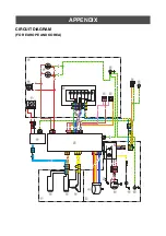
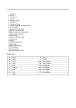
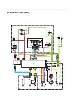
Page 101: ... control switch 12 Boost mode switch Reset button 13 Ground Earth terminal 14 Engine switch 15 Fuel cock ground earth 16 Control unit 17 Engine 18 Throttle control motor 19 Spark plug 20 CDI unit Ignition coil 21 CDI magneto 22 Oil level switch 23 Ground Earth terminal B Black W White Br Brown Y Yellow G Green Br B Brown Black Gy Gray G Y Green Yellow L Blue L B Blue Black O Orange R W Red White P...

Page 102: ...O B R W R W Br B Y Y B Y L R R R B O L L G Y Y B L B O L L B L L B L L Y B L B Y Y Y Y Y Y R Br O R G Y Br R G Y Y Br R W Y B G Y G Y G Y G Y O G Y Br B O R Br G Y R Br P G Y P G Y G Y V L Br R W B W Br B G L Gy Gy Br B V W B G Br P O V W L W B L B Y B t r w e q 0 9 8 6 5 y 1 2 3 4 u a o p s d i 7 ...

Page 103: ... control switch 12 Boost mode switch Reset button 13 Ground Earth terminal 14 Engine switch 15 Fuel cock ground earth 16 Control unit 17 Engine 18 Throttle control motor 19 Spark plug 20 CDI unit Ignition coil 21 CDI magneto 22 Oil level switch 23 Ground Earth terminal B Black W White Br Brown Y Yellow G Green Br B Brown Black Gy Gray G Y Green Yellow L Blue L B Blue Black O Orange R W Red White P...

Page 104: ... 4 5 6 7 8 9 10 ELECTRICAL ELECTRICAL COMPONENTS 1 Engine switch 2 CDI magneto 3 CDI unit ignition coil 4 Oil level switch 5 AC DC converter 6 Control unit 7 Spark plug 8 Generator assembly 9 Throttle control motor 8 2 3 4 5 7 9 1 6 ...

Page 105: ...ve the parts in the order listed Front cover 1 2 rear cover 1 2 side cover left right and fuel tank Refer to COVERS AND FUEL TANK on page 2 3 1 Control unit 1 2 AC DC converter 1 3 Control unit cover 1 4 Fuel tank bracket 1 1 2 3 4 7 N m 0 7 kgf m 5 2 lb ft 1 8 N m 0 18 kgf m 1 3 lb ft 7 N m 0 7 kgf m 5 2 lb ft 1 3 N m 0 13 kgf m 0 95 lb ft ...

Page 106: ...e switch TIP Before checking for continuity set the digital circuit tester to the range When checking for continuity switch back and forth between the switch positions a few times Measurement example of the electric components 1 2 a Ω O L Never insert the tester probes into the coupler termi nal slots Always insert the probes from the opposite end of the coupler taking care not to loosen or dam ag...

Page 107: ...ng starting with step 3 Refer to ENGINE DOES NOT START on page 6 4 TIP If the ignition spark gap is within specification the ignition system circuit is operating normally a Disconnect the spark plug cap 1 from the spark plug b Connect the ignition checker 2 as shown c Connect the ignition checker lead to spark plug 3 as shown d Pull the recoil starter handle e Measure the ignition spark gap a W W ...

Page 108: ...e digital circuit tester to the spark plug cap as shown c Measure the spark plug cap resistance CHECKING THE IGNITION COIL CDI UNIT IGNITION COIL RESISTANCE 1 Check Secondary coil resistance Out of specification Replace Spark plug cap resistance 3 75 6 25 k 1 2 Model 88 Multimeter with tachometer YU A1927 Digital circuit tester CD732 90890 03243 Positive tester probe Spark plug side 1 Negative tes...

Page 109: ...ircuit tester to the charge coil terminal c Measure the charge coil resistance 2 Check Pulsar coil resistance Out of specification Replace B Br R W 1 2 Model 88 Multimeter with tachometer YU A1927 Digital circuit tester CD732 90890 03243 Positive tester probe High tension cord 1 Negative tester probe Black terminal 2 Charge coil resistance 315 385 B Br R W 1 2 Model 88 Multimeter with tachometer Y...

Page 110: ...cation Replace a Connect the digital circuit tester to the oil level switch as shown b Check the oil level switch continuity B Br R W 1 2 Model 88 Multimeter with tachometer YU A1927 Digital circuit tester CD732 90890 03243 Positive tester probe Red White terminal 1 Negative tester probe Black terminal 2 1 1 2 2 Model 88 Multimeter with tachometer YU A1927 Digital circuit tester CD732 90890 03243 ...

Page 111: ...coil AC voltage CHECKING THE MAIN COIL RESISTANCE 1 Measure Main coil resistance Out of specification Replace the stator assembly a Stop the engine b Connect the digital circuit tester to yellow leads c Measure the main coil resistance Y Y Y Y Y Y R T S Main coil AC voltage 326 488 V 4900 r min Model 88 Multimeter with tachometer YU A1927 Digital circuit tester CD732 90890 03243 Y Y Y R T S Main c...

Page 112: ...e the sub coil AC voltage CHECKING THE SUB COIL RESISTANCE 1 Measure Sub coil resistance Within specification Replace the control unit Out of specification Replace the stator assembly a Stop the engine b Connect the digital circuit tester to orange leads c Measure the sub coil 1 resistance O O L L O O L L 1 Sub coil AC voltage 16 24 V 4900 r min Model 88 Multimeter with tachometer YU A1927 Digital...

Page 113: ...C coil AC voltage CHECKING THE DC COIL RESISTANCE 1 Measure DC coil 1 resistance Within specification Replace the AC DC con verter Out of specification Replace the stator assembly a Stop the engine b Connect the digital circuit tester to blue leads c Measure the DC coil resistance O O L L O O L L 1 DC coil AC voltage 29 43 V 4900 r min Model 88 Multimeter with tachometer YU A1927 Digital circuit t...

Page 114: ... circuit tester to throttle control motor lead coupler b Measure the throttle control motor coil resis tance 4 Check Wire harness Terminal of the connector Good condition Replace the throttle control motor Contamination rust or disconnection Connect or replace the connector or wire harness 1 2 3 4 5 1 2 3 4 5 Throttle control motor coil resistance 232 5 267 5 at 25 C 77 F Model 88 Multimeter with ...

Page 115: ...onnector Contamination rust or disconnection Clean or replace the connector 1 2 1 Overload indicator light 2 Reset button Power output Overload indicator light Engine rotation Description Action Stops Flashes Decreases Control unit out of order Replace the control unit Stops Comes on Decreases If reset is impossible even if the reset button is pressed for 3 seconds a serious malfunction may be con...

Page 116: ...ELECTRICAL COMPONENTS 5 17 1 2 3 4 5 6 7 8 9 10 ELECTRICAL MEMO ...

Page 117: ... coil resistance Model 88 Multimeter with tachometer YU A1927 Digital circuit tester CD732 90890 03243 Checking steps Possible remedy Check the overload indicator light comes on Comes on Refer to OVERLOAD WARNING on page 2 30 Does not comes on Proceed to step 2 Checking steps Possible remedy Check the output indicator comes on Comes on Proceed to step 3 Does not comes on Replace the multi function...

Page 118: ...ge 5 12 Good Proceed to step 7 Too low Replace the generator rotor Does not generate Proceed to step 6 Checking steps Possible remedy Check the main coil resistance Refer to CHECKING THE MAIN COIL RESIS TANCE on page 5 12 Good Proceed to step 7 Out of specification Replace the stator assembly Checking steps Possible remedy Check the sub coil AC voltage Refer to CHECKING THE SUB COIL AC VOLT AGE on...

Page 119: ...he multi function LED meter Checking steps Possible remedy 1 Operate the engine with no load 2 Measure after warming up the engine 3500 r min Economy control switch I ON 4900 r min Economy control switch OFF Good Proceed to step 4 Out of specification Refer to CHECKING THE THROTTLE CONTROL SYSTEM on page 5 15 Checking steps Possible remedy Check the DC coil AC voltage Refer to CHECKING THE DC COIL...

Page 120: ...ignition system s wiring No Checking steps Possible remedy 1 Check the fuel level Add the fuel if it is insufficient 2 Check if the fuel tank strainer is clogged Clean or replace 3 Check if the fuel hoses are clogged Clean 4 Check if there is air suction from the carburetor assembly joint gasket or throttle shaft Tighten the carburetor assembly nuts securely Replace the carburetor assembly joint o...

Page 121: ...g steps 6 Check the valve face and valve seat for wear Refer to VALVE on page 3 21 Resurface or replace the valve face and valve seat 7 Check if the marks on the crankshaft and camshaft are aligned Refer to INSTALLING THE VALVE LIFTERS AND CAM SHAFT on page 3 31 Correct 8 Check if there is seizure wear or damage on the piston piston ring or cylinder Refer to PISTON CONNECTING ROD CRANKSHAFT AND CR...

Page 122: ...carburetor assembly joint or gasket with a new one 5 Check if the main passages such as the carburetor assem bly are clogged Clean the parts 6 Measure the valve clearance Refer to ADJUSTING THE VALVE CLEARANCE on page 2 21 Adjust the valve clearance 7 Check the valve face and valve seat for wear Refer to VALVE on page 3 21 Resurface or replace the valve face and valve seat 8 Check if there is seiz...

Page 123: ... 22i For Australia and Korea Engine type Air cooled 4 stroke gasoline OHV Cylinder arrangement Inclined 1 cylinder Displacement 0 079 L 79 cm Bore Stroke 48 6 43 0 mm 1 91 1 69 in Compression ratio 8 9 1 Standard compression pressure 800 950 kPa 8 0 9 5 kg cm 116 137 75 psi Operating hours Rated load 4 2 Hrs 50 Hz For Europe Australia and China 4 2 Hrs 60 Hz For Korea Fuel Unleaded gasoline Gasoho...

Page 124: ...ion Rated power factor 1 0 Frequency variation Instantaneous Less than 1 Setting Less than 0 1 Setting time Less than 0 1 sec Voltage fluctuation Instantaneous Less than 20 Setting Less than 3 Setting time Less than 2 sec AC output Voltage 230 V For Europe Australia and China 220 V For Korea Frequency 50 Hz For Europe Australia and China 60 Hz For Korea Rated output 1 8 kVA Rated current 7 8 A For...

Page 125: ...vel is measured when the economy control switch is turned to I ON LWAg shows the sound power level under the ISO3744 satisfied test conditions The noise level may vary in different environments Noise Level The figures quoted are emission levels and are not necessarily safe working levels Whilst there is a correlation between the emission and exposure levels this cannot be used reliably to determin...

Page 126: ...eter 11 996 12 000 mm 0 4723 0 4724 in Limit 11 976 mm 0 4715 in Piston ring Top ring Type Barrel Dimensions 1 5 1 9 mm 0 059 0 074 in End gap installed 0 15 0 30 mm 0 0059 0 0118 in Limit 0 55 mm 0 021 in Side clearance 0 04 0 08 mm 0 0016 0 0031 in Limit 0 12 mm 0 0047 in 2nd ring Type Taper Dimensions 1 5 1 9 mm 0 059 0 074 in End gap installed 0 25 0 40 mm 0 0098 0 0157 in Limit 0 75 mm 0 0295...

Page 127: ...eight Intake 20 540 0 05 mm 0 81 0 002 in Limit 20 39 mm 0 802 in Lobe height Exhaust 20 540 0 05 mm 0 81 0 002 in Limit 20 39 mm 0 802 in Base circle diameter Intake 16 189 0 05 mm 0 64 0 002 in Limit 16 039 mm 0 631 in Base circle diameter Exhaust 16 189 0 05 mm 0 64 0 002 in Limit 16 039 mm 0 631 in Camshaft journal diameter 11 965 11 990 mm 0 4711 0 4720 in Limit 11 95 mm 0 4705 in Valve Valve...

Page 128: ...earance Intake 0 052 mm 0 0020 in Stem to guide clearance Exhaust 0 052 mm 0 0020 in Valve clearance cold Intake 0 07 0 12 mm 0 0028 0 0047 in Exhaust 0 07 0 12 mm 0 0028 0 0047 in Push rod Runout limit 0 5 mm 0 02 in Valve spring Valve spring free length Intake 26 5 mm 1 0433 in Valve spring free length Exhaust 26 5 mm 1 0433 in Limit Intake 25 18 mm 0 9913 in Limit Exhaust 25 18 mm 0 9913 in Ins...

Page 129: ...DC 33 Spark plug type BPR6HS NGK Spark plug gap 0 6 0 7 mm 0 024 0 028 in Secondary coil resistance 2 92 3 57 k Spark plug cap resistance 3 75 6 25 k Minimum ignition spark gap 6 0 mm 0 236 in Charge coil resistance 315 385 Pulsar coil resistance 13 5 16 5 GENERATOR Generator Main coil AC voltage 3 phase 326 488 V 4900 r min Sub coil AC voltage single phase 16 24 V 4900 r min DC coil AC voltage 29...

Page 130: ... ft 2nd 11 N m 1 1 kgf m 8 1 lb ft CDI unit ignition coil bolt M6 1 0 4 5 N m 0 45 kgf m 3 3 lb ft CDI magneto bolt M6 1 0 10 N m 1 0 kgf m 7 4 lb ft Flywheel nut M12 1 25 40 N m 4 0 kgf m 30 lb ft Fan case cover bolt M6 1 0 7 N m 0 7 kgf m 5 2 lb ft Stator assembly bolt M6 1 0 10 N m 1 0 kgf m 7 4 lb ft Generator rotor nut M12 1 25 40 N m 4 0 kgf m 30 lb ft Generator fan bolt M6 1 0 7 N m 0 7 kgf...

Page 131: ...h Reset button 0 3 N m 0 03 kgf m 0 22 lb ft AC receptacle screw 0 5 N m 0 05 kgf m 0 37 lb ft Ground Earth terminal 1 3 N m 0 13 kgf m 0 95 lb ft Throttle control motor screw 1 0 N m 0 10 kgf m 0 73 lb ft Motor bracket screw 1 7 N m 0 17 kgf m 1 3 lb ft Float chamber bolt 7 N m 0 7 kgf m 5 2 lb ft Carburetor fuel drain cock screw 1 3 N m 0 13 kgf m 0 95 lb ft Choke cable nut 2 5 N m 0 25 kgf m 1 ...

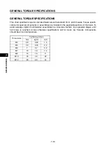
Page 132: ... assemblies are included in the applicable sections of this book To avoid warpage tighten multi fastener assemblies in a crisscross fashion in progressive stages until full torque is reached Unless otherwise specifications call for clean dry threads Components should be at room temperature Thread size Tightening torque N m kgf m lb ft M4 2 0 0 20 1 5 M5 3 0 0 30 2 2 M6 7 0 7 5 2 M7 10 1 0 7 4 M8 1...

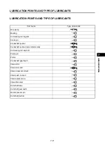
Page 133: ...ing Connecting rod big end Crank pin Crankshaft journal Crankshaft journal recoil starter side Connecting rod cap bolt Piston pin Piston Crankshaft gear teeth Valve stem Valve stem end Valve rocker arm shaft Valve push rod end Valve adjust screw Valve lifter stem Camshaft lobe Camshaft gear teeth Decompressor pin Camshaft journal LS E E E M M E E E E E M E E E E E E E E ...

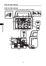
Page 134: ...WIRE ROUTING DIAGRAM 7 12 1 2 3 4 5 6 7 8 9 10 SPECIFICATIONS WIRE ROUTING DIAGRAM CONTROL PANEL AND CONTROL BOX FOR EUROPE AND KOREA ...

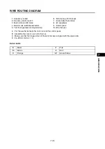
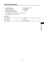
Page 135: ...ter 8 AC receptacle 4 Boost mode switch Reset button 9 Control panel 5 Twin Tech parallel running terminal 10 Wire harness A Put the washer between the resin nut and the control panel B Assemble the cover so as not to float up C Make sure that the hinge portion of the terminal cap is aligned with the upper side D 24 28 mm 0 94 1 1 in B Black P Pink Br Brown R Red O Orange G Y Green Yellow ...

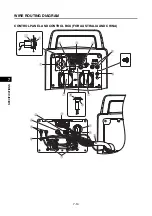
Page 136: ...WIRE ROUTING DIAGRAM 7 14 1 2 3 4 5 6 7 8 9 10 SPECIFICATIONS CONTROL PANEL AND CONTROL BOX FOR AUSTRALIA AND CHINA ...

Page 137: ...omy control switch 7 AC receptacle 3 Multi function LED meter 8 Control panel 4 Boost mode switch Reset button 9 Wire harness 5 Twin Tech parallel running terminal A Put the washer between the resin nut and the control panel B Assemble the cover so as not to float up B Black P Pink Br Brown R Red O Orange G Y Green Yellow ...

Page 138: ...WIRE ROUTING DIAGRAM 7 16 1 2 3 4 5 6 7 8 9 10 SPECIFICATIONS ENGINE AND GENERATOR ...

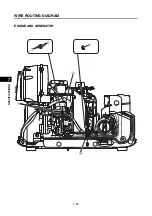
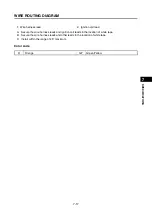
Page 139: ...e 1 Wire harness lead 2 Ignition coil lead A Secure the wire harness leads and ignition coil leads in the location of white tape B Secure the wire harness leads and other leads in the location of white tape C Install within the range of 45 maximum O Orange G Y Green Yellow ...

Page 140: ...WIRE ROUTING DIAGRAM 7 18 1 2 3 4 5 6 7 8 9 10 SPECIFICATIONS UPPER SIDE AND LEFT SIDE VIEW ...

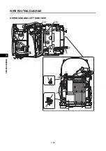
Page 141: ...re harness 2 Generator output lead 4 Control unit A Route the throttle control motor lead as shown in the illustration B Route the generator output lead as shown in the illustration C To control unit D To control panel E Insert the protrusion of the control unit into the hole and install it G Y Green Yellow ...

Page 142: ...WIRE ROUTING DIAGRAM 7 20 1 2 3 4 5 6 7 8 9 10 SPECIFICATIONS CONTROL UNIT ...

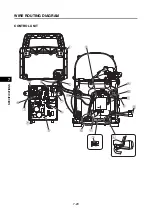
Page 143: ...r leads together and insert them into the holes in the cover B Pass the throttle control motor lead through a hole indicated by diagonal lines C To control unit D To control unit E Routing details F Install within the range of 45 maximum G Pass the AC DC ground wire AC DC input wire oil level warning light lead wire and engine ground wire through the hole shown in the illustration H To generator I...

Page 144: ...WIRE ROUTING DIAGRAM 7 22 1 2 3 4 5 6 7 8 9 10 SPECIFICATIONS GENERATOR ...

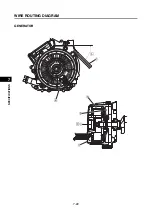
Page 145: ...AGRAM 7 23 1 2 3 4 5 6 7 8 9 10 SPECIFICATIONS 1 Clamp 4 Generator grommet 2 Generator assembly 5 Rear end cover 3 Generator fan A Install within the range of 45 B Wire harness routing position C Insert until it hits ...

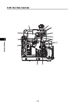
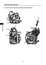
Page 146: ...WIRE ROUTING DIAGRAM 7 24 1 2 3 4 5 6 7 8 9 10 SPECIFICATIONS UPPER SIDE AND AIR FILTER SIDE VIEW ...

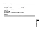
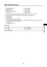
Page 147: ...then tighten the nut D Choke cable holder mounting details E When connecting the choke cable to the carburetor make the choke knob in the position shown Open 2 mm 0 08 in from the fully pressed position F Install the throttle control motor cover only after wiring of the throttle control motor is complete G Pass the inner cable through the wiring terminal hole of the choke shaft with the choke valv...

Page 148: ...WIRE ROUTING DIAGRAM 7 26 1 2 3 4 5 6 7 8 9 10 SPECIFICATIONS CARBURETOR AND AIR FILTER ...

Page 149: ...ir filter case joint 5 Carburetor assembly 12 Air filter case gasket 6 Crankcase 13 Pipe 1 7 Seal 14 Clip A Insert it until its end position B Clip assembly details C The clip should be assembled in a position that surely exceeds the expansion part of the pipe D Insert the hose between the air filter case and the air filter case cover as shown E Install the pipe 1 within the range of 45 30 ...

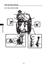
Page 150: ...WIRE ROUTING DIAGRAM 7 28 1 2 3 4 5 6 7 8 9 10 SPECIFICATIONS FUEL TANK AND FUEL HOSES ...

Page 151: ... Clip 13 Clip 7 Fuel hose fuel tank to fuel cock 14 Carburetor assembly A Push the rubber damper into the hole of rear cover 2 B Push the rubber damper into the hole of front cover 2 C Details of fuel hose routing D White paint E Yellow paint F Details of carburetor fuel drain cock and hose routing G Yellow paint H Insert the fuel drain hose into the hole I Sectional view of the carburetor fuel dr...

Page 152: ...WIRE ROUTING DIAGRAM 7 30 1 2 3 4 5 6 7 8 9 10 SPECIFICATIONS ...

Page 153: ... Fuel tank 5 Engine switch together with fuel cock 2 Clip 6 Carburetor assembly 3 Fuel pump 7 Pulsar hose 4 Fuel hose fuel cock to fuel pump 8 Fuel hose fuel pump to carburetor A White paint B Install the fuel hose as shown C Install the ground earth lead as shown ...

Page 154: ...WIRE ROUTING DIAGRAM 7 32 1 2 3 4 5 6 7 8 9 10 SPECIFICATIONS OIL LEVEL SWITCH CRANKCASE COVER AND CDI MAGNETO 10 10 ...

Page 155: ...ad clamp 4 Flywheel A Twist the high tension cord in until it comes in contact with the spark plug cap B To control box C Clamp the high tension cord as shown D Connect the CDI magneto lead wire so that it is not slack or caught E Spark plug cap installation area F Route the oil level switch lead as shown G Push the lead wire grommet of the oil level switch against the gray tube ...

Page 156: ...OPE AND KOREA O R G Y G Y Br R Y W R W B Br B G O G Y G Y G Y G Y Y Br Br L G Y Gy B O Gy R Br B V W B Br G Y R Br P G Y G P G Y Br P O V G Y W V L L W B L B Y B R W Br B R B L L O O Y Y Y t r w e q 0 9 8 6 5 y 1 2 3 4 u a o p s d i 7 ...

Page 157: ...ode switch Reset button 13 Ground Earth terminal 14 Engine switch 15 Fuel cock ground earth 16 Control unit 17 Engine 18 Throttle control motor 19 Spark plug 20 CDI unit Ignition coil 21 CDI magneto 22 Oil level switch 23 Ground Earth terminal B Black W White Br Brown Y Yellow G Green Br B Brown Black Gy Gray G Y Green Yellow L Blue L B Blue Black O Orange R W Red White P Pink W B White Black R Re...

Page 158: ...NA O R G Y Br R G Y Y Br R W Y B G Y G Y G Y G Y O G Y Br B O R Br G Y R Br P G Y P G Y G Y V L Br R W B W Br B G L Gy Gy Br B V W B G Br P O V W L W B L B Y B R B L L O O Y Y Y t r w e q 0 9 8 6 5 y 1 2 3 4 u a o p s d i 7 ...

Page 159: ...ode switch Reset button 13 Ground Earth terminal 14 Engine switch 15 Fuel cock ground earth 16 Control unit 17 Engine 18 Throttle control motor 19 Spark plug 20 CDI unit Ignition coil 21 CDI magneto 22 Oil level switch 23 Ground Earth terminal B Black W White Br Brown Y Yellow G Green Br B Brown Black Gy Gray G Y Green Yellow L Blue L B Blue Black O Orange R W Red White P Pink W B White Black R Re...

Page 160: ...MEMO ...

Page 161: ...7PC F8197 E0_Hyoshi indd 3 4 2019 08 28 16 31 47 ...
Page 162: ...SERVICE MANUAL EF2200iS 7PC F8197 E0 2019 09 1 E 7PC F8197 E0_Hyoshi indd 1 2 2019 08 28 16 31 47 ...
Reviews: