1
2
3
4
5
6
7
8
9
10
P
E
RIODIC
CH
ECKS AND ADJUSTMENTS
2-1
PERIODIC CHECKS AND ADJUSTMENTS
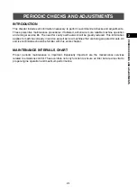
INTRODUCTION
This chapter includes all information necessary to perform recommended checks and adjustments.
These preventive maintenance procedures, if followed, will ensure more reliable machine operation
and a longer service life. The need for costly overhaul work will be greatly reduced. This information
applies to machines already in service as well as new machines that are being prepared for sale. All
service technicians should be familiar with this entire chapter.
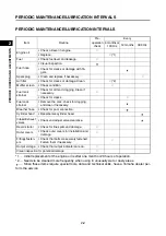
MAINTENANCE INTERVALS CHART
Proper periodic maintenance is important. Especially important are the maintenance services
related to emissions control. These controls not only function to ensure air filter but are also vital to
proper engine operation and maximum performance.
Summary of Contents for EF2200iS
Page 2: ...7PC F8197 E0_Hyoshi indd 3 4 2019 08 28 16 31 47 ...
Page 18: ...SPECIAL TOOLS AND TESTERS 1 8 1 2 3 4 5 6 7 8 9 10 GENERAL INFORMATION MEMO ...
Page 50: ...PERIODIC MAINTENANCE 2 32 1 2 3 4 5 6 7 8 9 10 PERIODIC CHECKS AND ADJUSTMENTS MEMO ...
Page 99: ...FUEL PUMP 4 7 1 2 3 4 5 6 7 8 9 10 CARBURETOR MEMO ...
Page 116: ...ELECTRICAL COMPONENTS 5 17 1 2 3 4 5 6 7 8 9 10 ELECTRICAL MEMO ...
Page 138: ...WIRE ROUTING DIAGRAM 7 16 1 2 3 4 5 6 7 8 9 10 SPECIFICATIONS ENGINE AND GENERATOR ...
Page 140: ...WIRE ROUTING DIAGRAM 7 18 1 2 3 4 5 6 7 8 9 10 SPECIFICATIONS UPPER SIDE AND LEFT SIDE VIEW ...
Page 142: ...WIRE ROUTING DIAGRAM 7 20 1 2 3 4 5 6 7 8 9 10 SPECIFICATIONS CONTROL UNIT ...
Page 144: ...WIRE ROUTING DIAGRAM 7 22 1 2 3 4 5 6 7 8 9 10 SPECIFICATIONS GENERATOR ...
Page 148: ...WIRE ROUTING DIAGRAM 7 26 1 2 3 4 5 6 7 8 9 10 SPECIFICATIONS CARBURETOR AND AIR FILTER ...
Page 150: ...WIRE ROUTING DIAGRAM 7 28 1 2 3 4 5 6 7 8 9 10 SPECIFICATIONS FUEL TANK AND FUEL HOSES ...
Page 152: ...WIRE ROUTING DIAGRAM 7 30 1 2 3 4 5 6 7 8 9 10 SPECIFICATIONS ...
Page 160: ...MEMO ...
Page 161: ...7PC F8197 E0_Hyoshi indd 3 4 2019 08 28 16 31 47 ...


