38
EMX66M
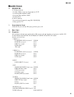
3.2
For the case that the POWER AMP switch is 'MAIN BRIDGE'
3.2.1 Preparation
•
POWER AMP switch: MAIN BRIDGE
•
INPUT terminal: CH 5 LINE 1
•
MASTER (MAIN): MAX
•
OUTPUT terminal: BRIDGE
•
Load Resistance: 8
Ω
(more than 600W)
Except otherwise indicated, the load resistance of SPEAKER should
be connected only for the amplifier check.
•
LEVEL control of CH1-4, 6: MIN
•
Except the above, same as the setting of 2.1
3.2.2 Gain Check
Apply -26.0dB signal into input terminal, and confirm that the output level of 22.0
±
2 dBs can be gained.
3.2.3 Frequency Response Check
Apply -26.0dBs signal into input terminal, and confirm that the output level for 20Hz, 20kHz signal are 1, -3dB from the
level for 1kHz signal.
4.
Miscellaneous
4.1
Power Supply Voltage Variation
Change the voltage of power supply in the range of
±
10%, and confirm that the system works normally.
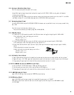
T
S
meter
Input
GND
Speaker
Terminal
Resistor
Resistor
4
Ω
4
Ω
Level
Summary of Contents for EMX66M
Page 5: ...5 EMX66M...
Page 6: ...6 EMX66M...
Page 26: ...26 EMX66M A A MIX66 Circuit Board...
Page 27: ...27 EMX66M A A Pattern side 3NA V826690 1...
Page 28: ...28 EMX66M to MIX66 CN901 DSP Circuit Board Component side 3NA V826710 1...
Page 29: ...29 EMX66M Pattern side 3NA V826710 1...
Page 39: ...39 EMX66M...
Page 40: ...40 EMX66M...
Page 41: ...41 EMX66M...
Page 42: ...42 EMX66M...
Page 43: ...43 EMX66M...
Page 44: ...44 EMX66M...


