background image

8

EMX7 Owner’s Manual

Quick Start Guide

Getting Sound to the Speakers/
Connection Example

Rear Panel

(See page 14.)

2.

3.

Passive

speakers

AC power 
cord

1.

Turn off (

) all switches (including the 

[

] (Power) switch).

2.

Connect the devices you intend to use.

(The diagram to the right shows a connection example. 
Also refer to the diagram to the left.)

Precautions for Connecting the Speakers

• Connect a single passive speaker (a speaker without an 

internal amplifier) to the respective [SPEAKERS A/B] 
jacks. Sending the signal from both [SPEAKERS A/B] 
jacks to a single speaker may result in malfunction.

• Make sure to insert the speaker cables all the way inside 

until secure.

• Use speaker cables that have insulated connector handles 

(housing).

• For details about speaker connection, see page 22.

3.

Connect the included power cord.

Connection order: 
Mixer [AC IN] jack 

 Power outlet

4.

Turn all [LEVEL] controls and MASTER 
[LEVEL] controls to “0” and set the equal-
izer controls to the [

] position.

5.

Set the [

MIC/

LINE] switch to the 

MIC” position for microphone con-

nection, and to the “

LINE” position for 

connection of an instrument or audio 
device. When connecting a condenser 
microphone, set the [P48V] 
switch to the ON position (

).

NOTE

When removing the power cord, do so in the reverse order.
(Power outlet 

 Mixer [AC IN] jack)

t

Microphone 
× 3

Electric bass guitar

Keyboard

Turn the [Hi-Z] switch on. 
(See section 

i

 on page 

12.)

Connection 
Example

Equalizer 

controls

Summary of Contents for EMX7

Page 1: ...Owner s Manual EN If you wish to get started right away If you encounter a problem pages 8 to 11 Quick Start Guide page 21 Troubleshooting ...

Page 2: ......

Page 3: ...n unused for long periods of time 14 Refer all servicing to qualified service personnel Servicing is required when the apparatus has been damaged in any way such as power supply cord or plug is dam aged liquid has been spilled or objects have fallen into the apparatus the apparatus has been exposed to rain or moisture does not operate normally or has been dropped UL60065_03 PRÉCAUTIONS CONCERNANT ...

Page 4: ...he Plug and Cord WARNING THIS APPARATUS MUST BE EARTHED IMPORTANT The wires in this mains lead are coloured in accordance with the fol lowing code GREEN AND YELLOW EARTH BLUE NEUTRAL BROWN LIVE As the colours of the wires in the mains lead of this apparatus may not correspond with the coloured markings identifying the terminals in your plug proceed as follows The wire which is coloured GREEN and Y...

Page 5: ... the speakers Do not use speakers for a long period of time at a high or uncomfortable volume level since this can cause permanent hearing loss If you experience any hearing loss or ringing in the ears consult a physician When turning on the AC power in your audio system always turn on the device LAST to avoid hearing loss and speaker damage When turning the power off the device should be turned o...

Page 6: ...sunlight near a heater or in a car during the day in order to prevent the possibility of panel disfiguration unstable operation or damage to the internal components Do not place vinyl plastic or rubber objects on the device since this might discolor the panel Place input cables for devices such as microphones and microphone amplifier circuits with high sensitivity in a location that is far away fr...

Page 7: ...nputs used to directly connect an instrument such as a guitar or bass guitar Compressor This product is equipped with the popular 1 knob COMP function used in MGP and MG series models By simply operating a single control it is possible to get optimal compression for vocals and instruments Comprehensive Professional Effects and Signal Processing This product is equipped with a powerful comprehensiv...

Page 8: ...peaker cables all the way inside until secure Use speaker cables that have insulated connector handles housing For details about speaker connection see page 22 3 Connect the included power cord Connection order Mixer AC IN jack Power outlet 4 Turn all LEVEL controls and MASTER LEVEL controls to 0 and set the equal izer controls to the position 5 Set the MIC LINE switch to the MIC position for micr...

Page 9: ...l sound level 9 If necessary adjust the balance of the connected devices using the LEVEL controls for channels 1 to 11 12 WARNING When turning off the power a loud and unpleasant noise may be generated by the speakers To prevent this first turn off the Mixer Power switch then turn off the instrument or audio device t Optimizing the volume settings When the volume is too loud Turn the LEVEL control...

Page 10: ...etter understand the performer s singing 1 Adjust the COMP controls until you get the desired sound for channels you wish to add compression Turn the control to the right to increase the level of compression Avoid setting the value too high as too much compression may lead to feedback Common Compressor Applications In addition to vocals the compressor can be used to enhance the sound of instrument...

Page 11: ...on Connect a control device such as the optional FC5 foot switch sold separately to the FOOT SW jack which lets you conveniently bypass enable the built in effects 4 Set the FX RTN LEVEL control to the position 5 Use the AUX2 FX send controls to adjust the effect depth for each channel you wish to apply the effect 6 Use the FX RTN LEVEL control to adjust the overall effect depth If you wish to cha...

Page 12: ...ion u HPF High Pass Filter switches Channels 1 3 Turning this switch on applies a high pass filter that attenuates frequencies below 80 Hz in the signal by a slope of 12 dB octave This function should be kept on when using vocals in order to reduce noise from vibration or wind picked up by the microphone i Hi Z switch Channel 4 Turn this switch on when you wish to connect instruments with passive ...

Page 13: ... in the performance 7 AUX1 SEND jack AUX2 SEND jack For connecting to a musician monitoring system external effect device and so on These are impedance balanced TRS phone type output jacks See the Jack and Plug List on page 26 8 STEREO OUT jacks These are TRS phone type impedance balanced output jacks that output the mixed stereo signal The signal level is adjusted by the STEREO MASTER LEVEL contr...

Page 14: ...ode selection determines the output signal For more information about selecting the amplifier mode see page 17 6 AC IN jack For connecting the included power cord here First connect the power cord to the mixer and then plug it into an outlet 7 USB terminal This is used only for performing maintenance It is not used during normal operation Rear Panel 5 6 7 Amplifier Mode Selection SPEAKERS A Jack S...

Page 15: ...ncoder When the Power switch is turned on When the PROGRAM rotary encoder is operated from any screen HOME screen The currently selected effect is displayed on the HOME screen For details about effect selec tion see Using the Built in Effects on page 11 SPEAKER PROCESSOR screen SYSTEM SETUP screen GEQ ON screen GEQ EDIT screen MENU screen Firmware version information Press the GEQ ACCESS button Fr...

Page 16: ...operation is detected for an extended period of time The program list includes the names of common Yamaha speakers etc NOTE When using a model of speaker that is not included in the program list select FLAT or any other setting that satisfies your sound quality requirements If you wish to return to the MENU screen turn the MENU CONTROL rotary encoder until the cursor highlights the MENU button and...

Page 17: ...parameter box is fully highlighted 4 Turn the MENU CONTROL rotary encoder to change the Amp Mode parameter You can choose between STEREO and L R AUX1 modes 5 Press the MENU CONTROL rotary encoder to confirm your selection The AMPLIFIER MODE indicators on the front panel show the current amplifier mode See section 2 on page 13 NOTE If you wish to return to the MENU screen turn the MENU CONTROL rota...

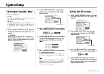
Page 18: ...der until the cursor highlights the BACKLIGHT parameter box 3 Press the MENU CONTROL rotary encoder so that the parameter box is fully highlighted 4 Turn the MENU CONTROL rotary encoder to set the Backlight parameter The brightness can be set to any value from 0 to 3 providing 4 different brightness levels Setting the LCD Backlight SYSTEM SETUP screen Parameter box 5 Press the MENU CONTROL rotary ...

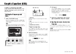
Page 19: ...er with maximum of 9 bands this shows the number of remaining bands that can be set 2 Select the frequency When the frequency value is highlighted turn the MENU CONTROL rotary encoder to select the desired frequency for adjusting the gain NOTE When the frequency value is not highlighted press the MENU CONTROL rotary encoder to highlight it and enable frequency selection GEQ EDIT screen q w e r 3 S...

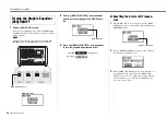
Page 20: ... the GEQ ON but ton 3 Press the MENU CONTROL rotary encoder to turn the graphic equalizer on or off GEQ ON button Highlighted When ON When OFF Resetting the Gain for All Frequen cies 1 When the GEQ ON screen is displayed turn the MENU CONTROL rotary encoder until the cursor highlights the RESET GEQ button 2 Press the MENU CONTROL rotary encoder to bring up the following confirmation screen 3 Turn ...

Page 21: ...nd the AUX1 AUX2 and STEREO MASTER LEVEL controls set to appropriate levels For channel 11 12 are both RCA and stereo mini jacks connected at the same time If both are connected the stereo mini jack will take priority Check that the speaker cables are not shorted The sound is low distorted or noisy Are all the input channel LEVEL controls and the AUX1 AUX2 and STEREO MASTER LEVEL controls set to a...
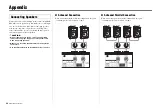
Page 22: ...peakers CAUTION When connecting each device only use appropriately rated cables and plugs Only use proper speaker cable when connecting speakers Make sure to insert the speaker cables all the way inside until secure Use speaker cables with an insulated housing connector 2 channel Connection When connecting using the following configuration use speak ers with impedance from 4 ohms to 8 ohms 4Ω to 8...

Page 23: ...l Orientation This is convenient when operating from a seated position with the mixer placed on the floor CAUTION Do not push too forcefully when tilting the mixer Excess force may cause the mixer to topple or turn potentially resulting in equipment damage or in injury to bystanders Installation This mixer has vents located on the sides Please install it so that these vents are well clear of walls...

Page 24: ...ter cool ing effect Refer to the rack and or fan kit manual for more details Rack Mounting CAUTION This mixer is heavy and should be lifted by two people when mounting onto a rack Assembly of the Rack mount Brack ets 1 Use a screwdriver to loosen and remove the 12 screws on the mixer side pads 2 Use six of the screws you removed in Step 1 to securely install the RK EMX7 separately sold rack mount ...

Page 25: ...e An effect which repeats the same sound only once Shortening the delay time produces a doubling effect 12 DELAY Delay Time Feedback delay adding multiple delayed signals 13 VOCAL ECHO Delay Time Echo designed for conventional vocals 14 KARAOKE Delay Time Echo designed for karaoke sing along applications 15 PHASER LFO Freq Cyclically changes the phase to add modulation to the sound 16 FLANGER LFO ...

Page 26: ...y Configuration MIC LINE Balanced MIC Balanced Pin 1 Ground Pin 2 Hot Pin 3 Cold XLR jack MIC LINE 1 Balanced Tip Hot Ring Cold Sleeve Ground TRS phone plug AUX1 SEND 1 Impedance balanced 2 AUX2 SEND 1 Impedance balanced 2 STEREO OUT 1 Impedance balanced 2 Tip Hot Ring Cold Sleeve Ground LINE 5 6 7 8 Unbalanced FOOT SW Unbalanced Tip Signal Sleeve Ground TS phone plug SPEAKERS A B Unbalanced Tip P...

Page 27: ...ingle control Threshold 22 dBu to 8 dBu Ratio 1 1 to 4 1 Output level 0 dB to 7 dB Attack time approx 25 ms Release time approx 300 ms Equalizer HIGH 10 kHz 15 dB Shelving MID 2 5 kHz 15 dB Peaking LOW 100 Hz 15 dB Shelving Level Meter 2 12 points LED meter 30 25 20 15 10 6 3 0 3 6 10 PEAK Phantom Power Voltage 48 V Built in Effect SPX Algorithm 24 programs FOOT SW Effect mute on off DSP Processin...

Page 28: ...Return LEVEL control 12 FX RTN Effect Return PARAMETER control 12 G Gain 19 20 GEQ ACCESS button 13 15 19 20 GEQ EDIT screen 15 19 GEQ ON button 20 GEQ ON screen 15 20 H Hi Z switch 8 12 HOME screen 11 15 HPF High Pass Filter switches 12 L LEVEL controls 12 Level meter 13 Level meter switch 13 LINE input jacks 12 M MENU button 15 MENU CONTROL rotary encoder 13 15 MENU screen 15 MIC input jacks 12 ...

Page 29: ...29 EMX7 Owner s Manual ...

Page 30: ...0 6686168 SWEDEN FINLAND ICELAND Yamaha Music Europe GmbH Germany filial Scandinavia JA Wettergrensgata 1 400 43 Göteborg Sweden Tel 46 31 89 34 00 DENMARK Yamaha Music Denmark Fillial of Yamaha Music Europe GmbH Tyskland Generatorvej 8C ST TH 2860 Søborg Denmark Tel 45 44 92 49 00 NORWAY Yamaha Music Europe GmbH Germany Norwegian Branch Grini Næringspark 1 1332 Østerås Norway Tel 47 6716 7800 RUS...

Page 31: ......

Page 32: ...al Development Department 2016 Yamaha Corporation Published 05 2016 POSG A0 Printed in Malaysia ZR75610 Yamaha Pro Audio global website http www yamahaproaudio com Yamaha Downloads http download yamaha com ...

Reviews: