background image

Summary of Contents for ET250

Page 1: ...n have a good knowledge of the new model and make best use of it in your sales and after service activities SERVICE DEPARTMENT YAMAHA MOTOR CO LTD NOTE _ The Research and Engineering Departments of Yamaha are continually striving to further perfect all models Improvements and modifications are therefore inevitable In light of this fact all specifications within this manual are subject to change wi...

Page 2: ...vides key information to make procedures easier or cleaner CAUTION A CAUTION indicates special procedures that must be followed to avoid change to the machine WARNING A WARNING indicates special procedures that must be followed to avoid injury to a machine operator or person inspecting or re pairing the machine ...

Page 3: ...ING DIAGRAM 20 A ENGINE 1 Left crank Due to use of a new type clutch the crankshaft is tapered at its end to mount the clutch 79 model 1 Left crank 8F3 11412 00 2 Bearing 93306 30605 3 Oil seal 93102 32161 Interchangeability No Refer to 8 Drive clutch As a result the bearing and oil seal in side diameters are changed from 32 mmto 30 mm 80 model 1 Left crank 8J2 11412 00l 2 8earing 93306 30617 3 Oi...

Page 4: ...Accordingly the insert for mounting of the air duct on the starter case is no longer used 1 Air duct No longer used 8G5 15471 001 2 Screw No longer used 98506 050081 3 Plainwasher H No longer used 92906 05200 4 Starter case 8F3 15711 01 2 NOTE The 1979 model can also be used without installing the air duct ...

Page 5: ...mplete 8H9 17610 00 2 Primary sliding sheave 18H9 17621 00l 3 Bushing 90389 39023 4 Cap 8H9 17631 00l 5 8ushing 90389 26022 6 Bolt 97311 06025 7 Boll 97311 06040 B Spring washer 92902 06100 9 Spider 8H9 17627 00 10 Slide 18A7 17653 00 11 Pin with hole 90240 07066 12 Plate washer 90201 06589 13 Weight 8H9 17632 001 14 Collar 90387 096981 Interchangeability 1980 ET250 2 15 Collar 90387 06697 16 Bolt...

Page 6: ...Steering gate 8H7 23871 00 __ 8 K3 23871 00 For easy assembling and maintenance the drive guard bracket is welded to the steering gate Interchangeability Yes 4 The previous model s steering gate 8H7 23871 00 is interchangeable as a set with the drive guard bracket 8F3 77316 01 L with the new steering gate NOTE Due to modifications in 1 and 2 above the 1979 model s drive guard bracket 1 8G5 77315 0...

Page 7: ... used 5 Tune up label 8K3 77743 00 As an aid to service a tune up label is attached to the intake silencer EI250 BKal SPECIFIKATIONER 1 BENSIN 2 MOTOROLJA 3 TANDSTIFT 4 ELEKTRODEAVSTAND 5 TANDINSTALLNING 6 LAoFART BRANSLEl JUSTERINGSSKRUV 7 TOMGANGSVARVTAL 8 BRANSLENIVA 9 KEDJEHUS OWEVOLYM OCH VISKOSITET 450 cc GEAR OLJA 10 VARITORAVSTAND 11 VARIATOR SIDOFORSKJUTNING 12 MATTSPANNING IS RlJd FOR YT...

Page 8: ...tion 80 model Yellow Bille ON ON LIGHT LIGHT Gray Black White Black Interchangeability No 2 Wire harness 8H7 82590 20 8K3 82590 20 For additional safety the headlight and taillight circuits are changed so that these lights are kept turned on as long as the engine is in operation Refer to 2 E Circuit Diagram Interchangeability No 6 3 Engine stop switch 8E3 83976 01 For additional safety the engine ...

Page 9: ... holder Tool name Primary shave 1 Removal a Remove the primary sheave mounting bolt using the sheave holder Primary fixed sheave puller bolt 1M18 P1 5 90890 01881 1 Sheave sub assembly tool 1 Primary fixed sheave puller bolt c Loosen the six bolts securing the primary sheave cap and sliding sheave d Remove the sheave subassembly tool The primary sheave cap and sliding sheave cap now be disassemble...

Page 10: ...Tool No X Free from grease Greasing point for free 90890 01877 Bushing tool Checkthtrspider and rollerfof slllooth movement and wear e Check both sheaves for warping If warped replace 4 Reassembly a Oil the points shown in the illustration Do not apply the grease on the portion of X mark For other parts greasing is unnecessary CAUTION If the U nut or cotter pin is removed for the greasing replace ...

Page 11: ...AUTION Make sure that the primary sheave cap assembly slides in contact with the fixed sheave boss 9 1980 ET250 e Clean the tapered portions of crankshaft and fixed sheave f Fit the fixed sheave to the tapered por _ tion of crankshaft g Apply engine oil to the threaded portion of primary sheave bolt and its contact surface with spring washer h Tighten the primary sheave mounting bolt using primary...

Page 12: ...exhaust pipe decarbonize a Spark plug condition gap and cleaning a a Tightening of the cylinder head a Tightness of bolts and nuts a a Wear on slide runners a a Primary drive system a a V belt a a Secondary drive system a a Sheave distance a a Sheave offset a a Brake pad wear a a Brake operation and adjustment a a Guide wheel rubber a a Wear of drive track wheel sprocket a a Initial 100km Drive tr...

Page 13: ...rand name 250mi 500 mil 1 000mi ENGINE Starter case 0 Oil pump control box 0 0 Aercsheil grease 7 A or Esso Beacon 325 grease Pump drive cover 0 0 Oil in the oiltank 0 YAMAL BF cvcle oi DRIVE Primary sheave weight 0 0 and roller pins Molybdenum disulfide Secondary shaft and 0 0 snowmobile grease sliding sheave Front axle housing 0 0 Shaft 1 and shaft 2 0 Light all purpose grease Slide rail 0 Drive...

Page 14: ...r head Combustion chamber volume with spark plug 32 1 crrr Compression chamber type Dome squish Head gasket thickness 0 5mm Cylinder Material Cast iron sleeves aluminum cylinder Bore size 73 mm Taper limit 0 05 mm 0 0020 in Out of round limit 0 01 mm 0 0004 in Piston Piston skirt clearance 0 045 0 050 mm Measuring point 10 mm from piston skirt end Piston over size 1st 73 25 mm 2nd 73 50 mm 3rd 73 ...

Page 15: ...S A 2 0 turns out Slow jet S J 50 Intermediate jet I J l 40 Starter jet St J 0 96 mm Fuel level F L 1 5 3 5 mm Idling engine speed 1 300 r min Main jet setting chart re 30D e 20 0 e io c 0 C to e 20 D e Altitude 22 F 4 QF 14 F 32 OF 50 DFI 68 Fl Sea level 138 mo 130 138 700m 130 14QOm 138 130 20GOm or more 138_ 125 130 Lubrication Autolube pump Color code Green Autolube pump Minimum stroke 0 20 0 ...

Page 16: ...nd number of teeth Polyethylene l1T Secondary drive Type Chain 40K l rretrOCfI6rirati6 Free play 10 5 mm 10 4 08 in 2 Chain housing oil quantity 450 em 15 21 oz Chain housing oil grade Gear oil API GL 3 SAE 75 or 80 Brake Type Disc brake Brake pad thickness 7 3 mm 10 29 in Brake pad wear limit 1 mm 10 04 in Gap between pad and disc 0 2 1 0 mm 0 008 0 039 in Chassis Frame Frame design and material ...

Page 17: ...er type with noise suppressor worse suppressor resistance 5 kn at 20 C 68 F C D I unit Model manufacturer 8H4 20 MITSUBISHI Lighting system Lighting output 12V l00W Lighting coil resistance 0 19f at 20 C 68 F Yellow Black Head light type Semi shield Bulb wattape q tv 12V 45 40W X 1 pc Tail brake light wattage 12V 8W 23W AC regulator Model manufacturer TRIZ 24B HITACHI or S8516B TOSHIBA Voltage 13 ...

Page 18: ... kq 18 ft lb Front axle IR H M20 Pl 0 80 Nm 18 0 m kg 58 ft Ibl Chain drive sprocket M12Pl 25 40 Nm 14 0 m kg 29 ft lb Use cotter pin Chain driven sprocket M8 Pl 25 25 Nm 12 5 m kg 18 ft Ibl Housing cap M8 Pl 25 15 Nm 11 5 m kq 11 ft tb Chain tensioner adjusting lock nut Ml0 P1 25 33 Nm 13 3 m kq 24 ft lb Sprocket wheel and front axle 5 Nm 10 5 m kg 3 5 ft Ibl Shaft 1 and frame Ml0 P1 25 55 Nm 15 ...

Page 19: ...n tool 90890 01135 4 Spacer p80 X 55 mm 90B90 OJ 818 5 a Crank installer bolt 90890 01275 5 b Crank installer bolt adaptor 90890 01280 M16 for Rightl 17 NO Description Tool No 5 c Crank installer bolt adaptor 90B90 01279 M 121 for Left 5 d Crank installer pot 90890 01274 6 Rotor holding tool 90890 01235 7 Sheave holder 90890 01880 8 Primary fixed sheave puller M 181 90890 01881 9 Sheave sub assemb...

Page 20: ...1980 ET250 E WIRE ROUTING DIAGRAM 18 ...

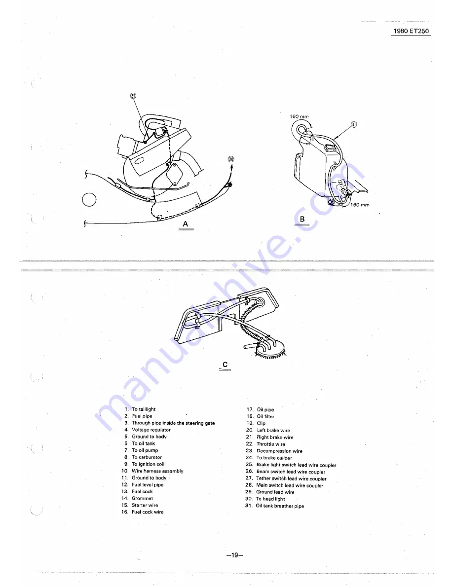
Page 21: ...d to body 12 Fuel level pipe 13 Fuel cock 14 Grommet 15 Starter wire 16 Fuel cock wire 19 17 Oil pipe 1a Oil filter 19 Clip 20 Left brake wire 21 Right brake wire 22 Throttle wire 23 Decompression wire 24 To brake caliper 25 Brake light switch lead wire coupler 26 Beam switch lead wire coupler 27 Tether switch lead wire coupler 28 Main switch lead wire coupler 29 Ground lead wire 30 To head light ...

Page 22: ...J a m i ot n a rl 2 G C G rl s a I Tether switch Beam switch Y Gy 0 L B 0 L Voltage regulator y P i y M H 1 I p c eDI I aneta B Color Code G Green B Black Y Yeliow L Blue o Orange Gy Gray Br Brown B W Black White WjR White Red Spark plug __ AV ...

Reviews: