background image

1

2

3

4

5

6

7

8

9

10

11

12

A

B

C

D

E

F

G

H

EZ-EG

EZ-EG

EZ-EG

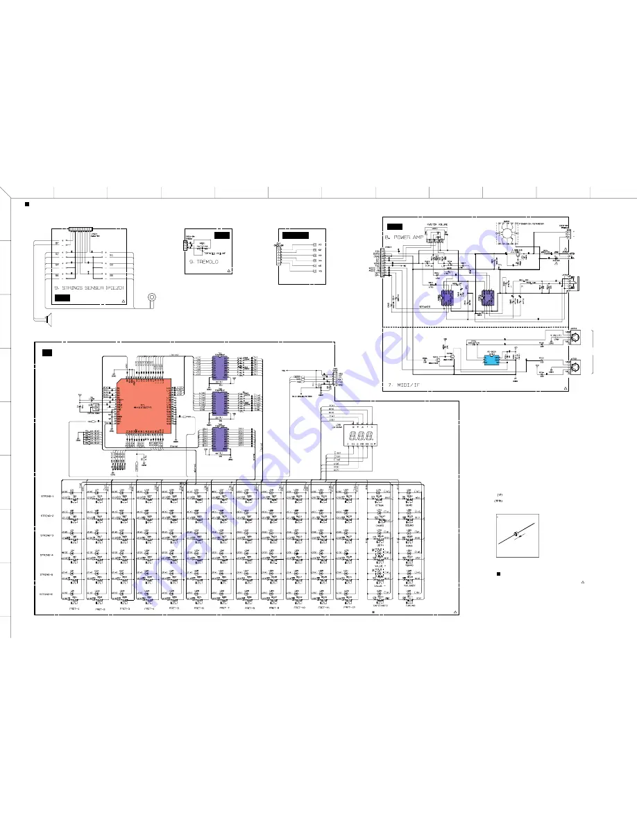
EZ-EG OVERALL CIRCUIT DIAGRAM 2/2 (AM-1, AM-2, AM-3, MUTE 1/2, PN)

AM-1

to DM-CN501

POWER AMP

PHOTO COUPLER

AM-2

to DM-CN601

AM-3

to DM-CN602

PIEZO SENSOR

PN

CPU

TRANSISTOR ARRAY

TRANSISTOR ARRAY

TRANSISTOR ARRAY

7-SEG. DISPLAY

to DM-CN701

MUTE 1/2

to DM-CN604

MIDI

PHONE/OUTPUT

DC-IN 9V

BATTERY

(SUM 3 x 6)

IN

OUT

28CA1-8822925

1

28CA1-8822925

1

28CA1-8822925

1

28CC1-8824158

28CA1-8822926

1

2A02M (VV731400)
DIODE

1

2

1: ANODE
2: CATHODE

SPEAKER

: Mylar Capacitor

: Semiconductive Cera Cap

S1~S6

not Installed

See parts list for details of circuit board
component parts.

Note: 

TO SERVICE PERSONNEL

Critical Components Information
Components having special characteristics are marked
and must be replaced with parts having specifications
equel to those originally installed.

!

本资料由OKXIA视听皮带资源库www.okxia.cn提供

Summary of Contents for EZ-EG

Page 1: ...DURE 7 LSI PIN DESCRIPTION 9 IC BLOCK DIAGRAM 11 CIRCUIT BOARDS 12 TEST PROGRAM 16 INSPECTIONS 18 MIDI IMPLEMENTATION CHART 19 PARTS LIST OVERALL CIRCUIT DIAGRAM HAMAMATSU JAPAN Copyright c Yamaha Corporation All rights reserved PDF K724 03 02 PK 011675 SERVICE MANUAL 本资料由OKXIA视听皮带资源库www okxia cn提供 ...

Page 2: ...es in specification are subject to change without notice or obligation to retrofit Should any discrepancy appear to exist please contact the distributor s Service Division WARNING Static discharges can destroy expensive components Discharge any static electricity your body may have accumulated by grounding yourself to the ground bus in the unit heavy gauge black wires connect to this bus IMPORTANT...

Page 3: ...H button DEMO button SOUND button SONG button TEMPO button BALANCE button CAPO button TUNING button VALUE buttons 18 additional songs can be loaded into internal memory from a computer 300 300 cents 32 280 0 127 0 10 28 tuning settings in addition to normal DC IN 9V PHONES OUTPUT mini stereo jack MIDI IN and MIDI OUT 0 7 W batteries or AC adaptor Output impedance 50 ohms 5 cm PA D09 AC Power Adapt...

Page 4: ...CE button 10 TUNING button 11 TEMPO button 12 CAPO button 13 SONG button 14 SOUND button 15 DEMO button 16 PLAY MODE 1 STRUM 2 CHORD 3 BOTH buttons 4 Tremolo Arm 5 VOLUME Control knob 6 STANDBY ON Control switch 17 MIDI IN MIDI OUT connectors 18 PHONES OUTPUT jack 19 DC IN 9V jack PANEL LAYOUT Body Control Section Connectors ...

Page 5: ...EZ EG 5 CIRCUIT BOARD LAYOUT Neck assembly Lower case assembly Strings sensor unit Body assembly AM 1 AM 3 AM 2 MUTE 1 2 DM PN CN3 CN1 CN901 CN902 CN801 CN701 CN604 CN501 CN601 CN602 Vibrato arm unit ...

Page 6: ...C DC CNV IC503 5V DC DC CNV IC504 MIDI Rx MIDI Tx TX RX 21 IC101 154 20 153 P Bus AN3 AN0 AN1 AN2 C bus S bus 47 48 51 59 62 71 41 74 23 34 37 40 TXD1 RXD1 TXD0 RXD0 145 147 150 152 5D 5D 14 15 16 4 14 15 17 5D 5 4 IC 9 10 1 3 3D SMA 0 20 SMD 0 15 SOE OE CE SCSO 24 IC201 PROGRAM 16M MASK IC301 3 3D 27 75 76 79 87 89 96 99 102 105 124 123 121 118 106 88 90 95 101 131 132 CMA 1 21 CMD 0 15 CMA 1 18 ...

Page 7: ...cuit board can then be removed Fig 4 4 Sensor Holder A Sensor Holder B Speaker AM 2 Circuit Board Time required about 25 minutes 4 1 Remove the lower case assembly See procedure 1 4 2 Remove the DM circuit board See procedure 3 4 3 Remove the four 4 screws marked 210 The two 2 stop per can then be removed Fig 5 4 4 Remove the four 4 screws marked 80 The sensor holder A and the sensor holder B can ...

Page 8: ...ve the DM circuit board See procedure 3 6 3 Remove the four 4 screws marked 110 The strings sen sor unit can then be removed Fig 6 6 4 Remove the vibrato arm unit See procedure 5 3 6 5 Remove the four 4 screws marked 60 The upper case can then be removed Fig 6 7 MUTE 1 2 Circuit Board MUTE 2 2 Circuit Board GS String Time required about 20 minutes 7 1 Remove the lower case assembly See procedure 1...

Page 9: ...can then be removed Fig 11 PIN NO I O FUNCTION NAME PIN NO I O FUNCTION NAME 1 2 3 4 5 6 7 8 9 10 11 12 13 14 15 16 17 18 19 20 21 22 23 24 25 26 27 28 29 30 31 32 S1 S2 S3 S4 S5 VREF VDD OSC2 OSC1 VSS XI XO MMOD RD0 RXD D0 D1 D2 D3 D4 RST D5 D6 D7 D8 D9 S6 S7 S8 S9 S10 S11 I I I I I O I I O I O I O O O O O I O O O O O I I I I I I Switch matrix data Power supply 5V analog Power supply 5V Crystal o...

Page 10: ...ess bus 85 86 87 88 89 90 91 92 93 94 95 96 97 98 99 100 101 102 103 104 105 106 107 108 109 110 111 112 113 114 115 116 117 118 119 120 121 122 123 124 125 126 127 128 129 130 131 132 133 134 135 136 137 138 139 140 141 142 143 144 145 146 147 148 149 150 151 152 153 154 155 156 157 158 159 160 161 162 163 164 165 166 167 168 CMA3 CMA8 CMA2 CRD CMA1 CUB VCC91 GHND92 CS1 CMA0 CLB CMA12 CMA11 CMA10...

Page 11: ...D 1 VDD 2 6A 3 6Y 4 5A 5 5Y 6 4A 7 4Y 1 Switches IN OUT 2 3 4 5 6 7 8 do Y0 do Z1 Z Z0 Commons OUT IN Swiches IN OUT Control Inhibit DC Voltage Supply do VDD Y X X1 X0 A B C 9 10 11 12 13 14 15 16 DC Voltage Supply Commons OUT IN Y do X Swiches IN OUT X1 do X0 Control Input A do B do C Y1 Y0 Z1 Z Z0 INH VEE VSS Y1 1 2 3 4 V 8 7 6 5 Output A V Non Inverting Input A Ground DC Voltage Supply Output B...

Page 12: ...o AM1 CN801 to AM2 CN901 to PN CN3 to AM3 CN902 2NA WA08980 V847030 3 CIRCUIT BOARDS AM 1 X2281C0 13 AM 2 X2281C0 13 AM 3 X2281C0 13 DM X3209A0 12 PN X2282C0 14 15 MUTE 1 2 X2284B0 13 MUTE 2 2 X2284B0 13 Note See parts list for details of circuit board component parts ...

Page 13: ... CN602 TREMOLO AM 1 Circuit Board AM 3 Circuit Board AM 2 Circuit Board MUTE 1 2 Circuit Board MUTE 2 2 Circuit Board POWER ON STANDBY VOLUME to DM CN601 to DM CN604 S6 S4 S2 S5 STRINGS SENSOR S3 S1 SPEAKER VR801 and SW801 are mounted in pattern side Do manual solder to JK801 after dip soldering AM 1 AM 2 AM 3 2NA V861530 MUTE 1 2 MUTE 2 2 2NA V938350 5 2 ...

Page 14: ...EZ EG 14 2NA V861540 1 1 Component side to DM CN701 PN Circuit Board A A A A B B B B STRING 1 STRING 2 STRING 3 STRING 4 STRING 5 STRING 6 ...

Page 15: ...40 2 1 Pattern side PN Circuit Board D D D D C C C C CAPO TEMPO TUNING BALANCE STRUM FRET 1 FRET 2 FRET 3 FRET 4 FRET 5 FRET 6 FRET 7 FRET 8 FRET 9 FRET 10 FRET 11 FRET 12 CHORD PLAY MODE DEMO SOUND SONG BOTH VALUE VALUE ...

Page 16: ...nd 3rd fret POWER ON STANDBY TEST No 1 2 3 4 6 11 13 14 15 19 7 seg LED for Each Test or or or or Test Function and Judgment criteria Displays the ROM version ROM Program Wave versions are displayed alternately on the LED Check the ROMs Checks all the ROMs that are connected to the CPU bus Check the RAMs Checks all the RAMs that are connected to the CPU bus Check the WAVE ROMs Checks the WAVE ROMs...

Page 17: ...ully play as the strings approach the 1st fret Note that the if a string is not played for more than 0 8 seconds the peak value is reset Check that the position of the fret LEDs that light up for each string are grouped within three segments of each other when the 1st through 6th strings are strummed at approximately the same force Checks 1 and 2 are performed simultaneously Tremolo check Attach t...

Page 18: ... unit performs normally by battery 6 Battery charger check Plug the AC adapter into the DC IN jack Then measure the voltage of the battery terminal Check that the main unit operates normally and that there is no voltage at the battery terminal 7 Static check Select Sound No 5 and play all strings with the MASTER VOLUME set to maximum and all other switches at their default settings Check that ther...

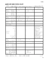
Page 19: ...wheel 6 38 x o Data Entry 7 o o Part Volume 10 o o Pan 11 x o Expression 64 Control x o Sustain 71 x o Harmonic Content 72 Change x o Release Time 73 x o Attack Time 74 x o Brightness 91 93 94 x x Effect Depth 96 97 x o RPN Inc Dec 100 101 x o RPN LSB MSB 84 o o Portamento Cntrl Prog o 0 127 o 0 127 Change True System Exclusive o 2 o 2 Song Pos x x Common Song Sel x x Tune x x System Real Time Clo...

Page 20: ...y 3 4 5 When the song is started an FAH message is transmitted When song is stopped an FCH message is transmitted When the clock is set to External both FAH song start and FCH song stop are recognized Local ON OFF Local ON Bn 7A 7F Local OFF Bn 7A 00 Value for n is ignored Song data is not transmitted Note str vel kno The value which is function ID ctr 1 ctr 2 str and kno are hexadecimal form stri...

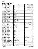
Page 21: ...ELECTRICAL PARTS 6 11 WARNING Components having special characteristics are marked and must be replaced with parts having specification equal to those originally installed Notes DESTINATION ABBREVIATIONS A Australian model B British model C Canadian model D German model E European model F French model H North European model I Indonesian model J Japanese model K Korean model M South African model O...

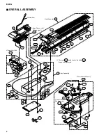
Page 22: ...ly Lower Case Assembly Lower Case Sub Assembly 10c 10b 10d 10 130 160 A10 A50 A40 A70 A30 A20 A60 120 Vibrato Arm Unit 50 100 110 N100 N90 N40 N30 N20 N110 N130a N130 N70 N80 N80 N60 N50 N10 70 Neck Assembly Strings Sensor Unit See page 4 Vibrato Arm 210 N70 The neck is attached to the body It cannot be removed 10a OVERALL ASSEMBLY ...

Page 23: ...30 N130a A10 A20 A30 A40 A50 A60 A70 L10 L10a L10b L90 L100 L120 V9561200 BB801510 VB793700 EN230140 V8519900 V8529300 V9501900 V8521700 V8525500 ET500040 V8523100 EP630220 V8524700 EP630220 V9401100 V9342600 AAX34830 AAX43860 EP630220 V8616100 V9547000 QC371700 WA161800 V8285200 V8285300 V8683000 X2289A00 V8521700 V8518700 V8520400 V8520600 V8520700 V8520900 AAX34870 EP630220 V8519300 V8519700 VE...

Page 24: ...0 80 80 21 20 30 200 210 210 50 150 160 190 140 130 180 180 230a 230b With a pattern With no pattern 10 190 70 280 270 STRINGS SENSOR UNIT Battery Cover Connector Assembly L130 L140 V8521800 C C 11P 160L V938330 01 New Parts RANK Japan only REF NO PART NO DESCRIPTION REMARKS QTY RANK ...

Page 25: ... 150 160 180 190 200 210 230 230a 230b 260 270 280 V8523100 X2279A00 V8615800 EP630220 AAX34850 EP630220 V8524500 V8524600 VG893800 VG893800 AAX34880 AAX39360 5cm SP L 60 WHITE RED 7BB12 9A6 3 0X8 MFZN2BL AM 2 3 0X8 MFZN2BL 1 0 GS 1 2 GS 1 0 1 2 2 0X6 MFZN2BL 2 0X6 MFZN2BL MUTE MUTE 1 2 MUTE 2 2 G 902S 15X50M 15X25 EZ EG V852350 V886700 V852320 V852330 Piezo V905470 V852360 V852740 V852380 V852390...

Page 26: ...00 V6223200 UR838470 V4271100 V6223200 V4271100 V4271100 V4270900 UR828220 UR828220 VV067100 VD631600 VV731400 VG181900 XM217A00 XM217A00 VS739900 VS739900 VS477200 V9280100 HF456100 HF455220 HF455220 HF457100 HF457220 HF457220 HF457330 HF456330 HF456330 HF457330 HF457100 HF457470 HF456100 HF455100 HF455100 HF454220 VI894000 VV457600 IC174020 IC174020 VH481100 V8614400 V8522100 V9401400 AAX34850 A...

Page 27: ...0506 C0507 C0508 C0509 C0510 C0511 C0512 C0513 C0514 C0515 C0521 C0522 C0525 C0526 C0527 C0528 C0529 C0530 C0531 C0601 0606 C0607 0612 C0613 0619 C0621 0626 C0630 0635 C0636 C0701 0703 C0704 0706 C0707 C0708 AAX34830 AAX43860 UX061270 UX061270 UX064100 UX064100 V4297100 UX064100 UX064100 V4297100 UX064100 UX064100 V4297100 UX064100 UX064100 V4297100 UX145100 UX064100 UX064100 UX064100 UX063100 UX0...

Page 28: ...38A00 X2363100 X2531300 X4181A00 X2343A00 X2310A00 XU720A00 XR998A00 XF634A00 XR404A00 XR858A00 XR532A00 XR532A00 XZ110A00 XV944A00 XW104A00 X3048A00 V8589900 V8589700 VL139600 RG005220 VY656700 VY656700 VL139600 RG008100 RG007100 RG007100 RG007100 RG007100 RG008390 RG008390 RG006560 RG007100 RG007100 RG008390 RG008390 RG006560 RG008100 RG007100 RG007100 RG008390 RG008390 RG006560 RG008100 RG00710...

Page 29: ...R0076 R0077 R0078 R0079 R0080 R0081 R0082 R0083 R0084 R0085 R0086 R0087 R0088 R0089 R0090 R0091 R0092 R0093 R0094 R0095 R0101 R0102 R0103 R0104 R0105 R0106 R0107 0110 R0111 R0112 R0113 R0114 R0115 R0116 R0117 0120 R0301 R0310 R0311 R0501 R0502 0504 R0505 R0506 0508 R0509 R0510 R0511 R0520 R0521 R0523 R0527 R0528 R0529 R0530 RG006560 RG008100 RG007100 RG007100 RG008470 RG008470 RG006560 RG008100 RG...

Page 30: ...0 V8573500 V8573500 V8573500 V8573500 V8573500 V8573500 V8573500 V8573500 V8573500 V8573500 10K 0 1 J 100K 0 1 J 4 7K 0 1 J 4 7K 0 1 J 680 0 1 J 680 0 1 J 10K 0 1 J 220 0 1 J 8 4672MHz SMD 49 UDZ 2 0BTE 17 2 0V UDZ 2 0BTE 17 2 0V PN 10 000 10V K 10 000 10V K 10 000 10V K 0 0100 50V K 100P 50V J 10 000 10V K M2426XX 5P TE 1SS355 TE 17 1SS355 TE 17 1SS355 TE 17 1SS355 TE 17 MN101C027YB KPH 1608SRC P...

Page 31: ...V KPH 1608SRC PRV KPH 1608SRC PRV KPH 1608SRC PRV KPH 1608SRC PRV KPH 1608SRC PRV KPH 1608SRC PRV KPH 1608SRC PRV KPH 1608SRC PRV KPH 1608SRC PRV KPH 1608SRC PRV KPH 1608SRC PRV KPH 1608SRC PRV KPH 1608SRC PRV KPH 1608SRC PRV KPH 1608SRC PRV KPH 1608SRC PRV KPH 1608SRC PRV KPH 1608SRC PRV KPH 1608SRC PRV KPH 1608SRC PRV KPH 1608SRC PRV KPH 1608SRC PRV KPH 1608SRC PRV KPH 1608SRC PRV KPH 1608SRC PR...

Page 32: ...M 256K x 16 AND MASK ROM 16M PROGRAM AND to MUTE CN1 J only to PN CN3 toAM 3 CN902 toAM 2 CN901 to AM 1 CN801 28CA1 8822924 1 Ceramic Capacitor µPC2933T E1 XS516A00 REGULATOR 3 3V MA221 VB493900 DIODE 1 V in 2 GND 3 V out 1 2 3 PQ1CZ1T XR404A00 DC DC CONVERTER SFPB 62V VZ060500 DIODE 4 3 2 1 5 3 OADJ 2 VOUT 4 ON OFFcont 5 COMMON 1 VIN 1 ANODE 2 CATHODE 2 1 2 1 1 ANODE 2 CATHODE UDZ 2 0BTE 17 2 0V ...

Page 33: ...NE OUTPUT DC IN 9V BATTERY SUM 3 x 6 IN OUT 28CA1 8822925 1 28CA1 8822925 1 28CA1 8822925 1 28CC1 8824158 28CA1 8822926 1 2A02M VV731400 DIODE 1 2 1 ANODE 2 CATHODE SPEAKER Mylar Capacitor Semiconductive Cera Cap S1 S6 not Installed See parts list for details of circuit board component parts Note TO SERVICE PERSONNEL Critical Components Information Components having special characteristics are mar...

Reviews: