6D45F11
5-44
9
8
7
6
5
4
3
2
1
7.
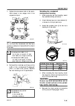
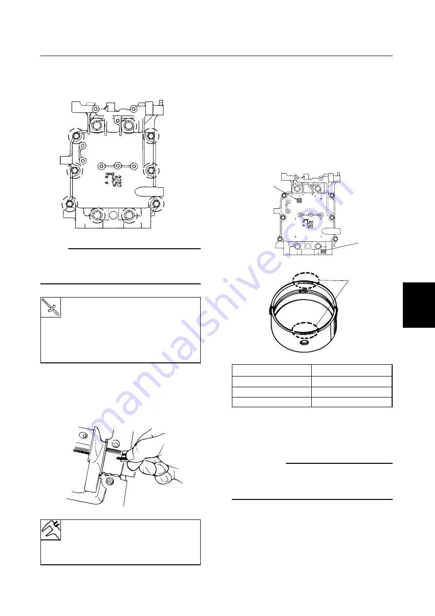
Tighten the crankcase bolts to the speci-
fied torques in two stages and in the
sequence shown.
NOTE:
Do not move the crankshaft until the main
journal oil clearance measurement has been
completed.
8.
Remove the crankcase and measure the
width of the compressed Plastigauge
®
(PG-1) on each main journal. Replace
the main bearing if out of specification.
Cylinder block
Selecting the crankshaft
main journal bearing
1.
When replacing the main bearing, select
the suitable bearing as follows.
2.
Check the bearing color code indicator
a
is marked on the cylinder block.
3.
Select the suitable color
b
for the main
bearing from the table.
4.
When installing the main bearing, insert
the projection of the main bearing into the
slot on the cylinder body.
c
C
Remove any small metal particles and oil
from the contact surfaces of the cylinder
body and the main bearing.
5.
Measure the main journal oil clearance
with a piece of Plastigauge
®
(PG-1).
Crankcase bolt (M8):
1
–
4
1st: 15 N·m (1.5 kgf·m, 11 ft·lb)
2nd: 30 N·m (3.0 kgf·m, 22 ft·lb)
Crankcase bolt (M6):
5
–
0
1st: 6 N·m (0.6 kgf·m, 4.4 ft·lb)
2nd: 12 N·m (1.2 kgf·m, 8.7 ft·lb)
6D451330
a
a
6D451380
b
6D451390
Crankshaft main journal
oil clearance:
0.012–0.045 mm
(0.0005–0.0018 in)
Cylinder body mark
Bearing color
A
Blue
B
Black
C
Brown
1
9
5
8
4
3
7
6
10
2
6D451035
0
9
8
7
6
5
4
3
2
1
6D45F11-05 03.10.9 20:44 Page 47

