6C13G11
7-50
1
2
3
4
5
6
7
8
9
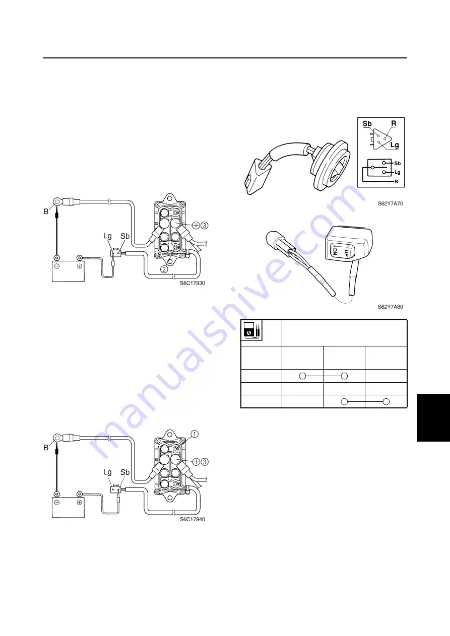
2.
Connect the digital circuit tester between
power trim and tilt relay terminals
2
and
3
.
3.
Connect the light green (Lg) lead to the
positive battery terminal and the black
(B) lead to the negative battery terminal
as shown.
4.
Check for continuity between terminals
2
and
3
. Replace if there is no continu-
ity.
5.
Connect the digital circuit tester between
power trim and tilt relay terminals
1
and
3
.
6.
Connect the sky blue (Sb) lead to the
positive battery terminal and the black
(B) lead to the negative battery terminal
as shown.
7.
Check for continuity between terminals
1
and
3
. Replace if there is no continu-
ity.
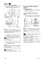
Checking the power trim and tilt
switch
1.
Check the power trim and tilt switch for
continuity. Replace if out of specification.
Lead color
Switch
position
Sky blue
(Sb)
Red (R)
Light green
(Lg)
Up
Free
Down
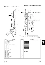
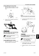
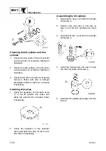
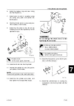
Tilt cylinder and trim cylinder / Power trim and tilt electrical system
Summary of Contents for F50F
Page 1: ...F50F FT50G F60C FT60D SERVICE MANUAL 6C1 28197 3G 11 290551 ...
Page 4: ......
Page 48: ...SPEC Specifications 2 25 6C13G11 MEMO ...
Page 190: ...LOWR Lower unit 6 47 6C13G11 Shimming FT50 FT60 6 ...
Page 195: ...6C13G11 6 52 1 2 3 4 5 6 7 8 9 MEMO Backlash FT50 FT60 ...
Page 221: ...6C13G11 7 24 1 2 3 4 5 6 7 8 9 Steering arm ...
Page 249: ...6C13G11 7 52 1 2 3 4 5 6 7 8 9 MEMO Power trim and tilt electrical system ...
Page 272: ...ELEC Electrical systems 8 21 6C13G11 MEMO ...
Page 301: ...6C13G11 i 5 1 2 3 4 5 6 7 8 9 Index MEMO ...
Page 303: ......
Page 304: ...YAMAHA MOTOR CO LTD Printed in the Netherlands Jul 2004 1 2 1 CR E_2 ...

