FUEL
Fuel system
4-7
6C13G11
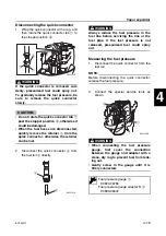
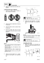
Checking the diaphragm and valves
1.
Check the diaphragm for tears and the
valves for cracks. Replace if necessary.
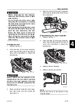
Assembling the fuel pump
NOTE:
Clean the parts and soak the valves and the
diaphragm in gasoline before assembly to
obtain prompt operation of the fuel pump
when starting the engine.
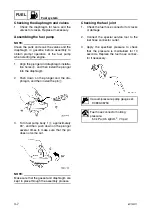
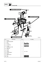
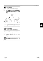
1.
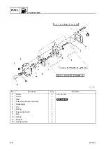
Align the plunger and diaphragm installa-
tion holes
a
, and then install the plunger
into the diaphragm.
2.
Push down on the plunger and the dia-
phragm, and then install the pin
1
.
3.
Turn fuel pump body 1
2
approximately
90°, and then push down on the plunger
several times to make sure that the pin
does not come out.
NOTE:
Make sure that the gasket and diaphragm are
kept in place through the assembly process.
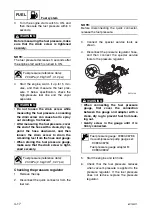
Checking the fuel joint
1.
Check the fuel hose connector for cracks
or damage.
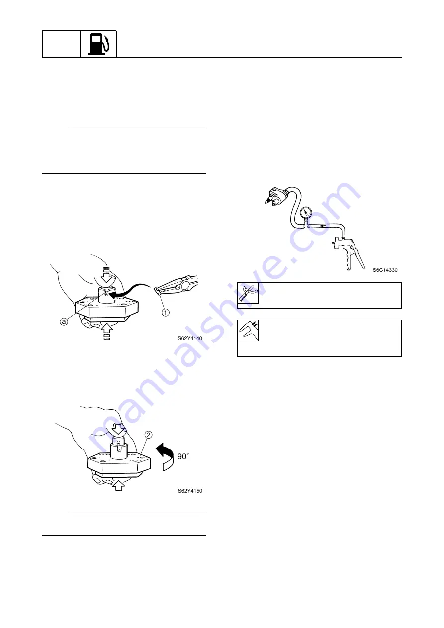
2.
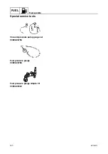
Connect the special service tool to the
fuel hose connector outlet.
3.
Apply the specified pressure to check
that the pressure is maintained for 10
seconds. Replace the fuel hose connec-
tor if necessary.
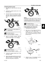
Vacuum/pressure pump gauge set:
90890-06756
Fuel hose connector holding
pressure:
50 kPa (0.5 kgf/cm
2
, 7.3 psi)
Summary of Contents for F50F
Page 1: ...F50F FT50G F60C FT60D SERVICE MANUAL 6C1 28197 3G 11 290551 ...
Page 4: ......
Page 48: ...SPEC Specifications 2 25 6C13G11 MEMO ...
Page 190: ...LOWR Lower unit 6 47 6C13G11 Shimming FT50 FT60 6 ...
Page 195: ...6C13G11 6 52 1 2 3 4 5 6 7 8 9 MEMO Backlash FT50 FT60 ...
Page 221: ...6C13G11 7 24 1 2 3 4 5 6 7 8 9 Steering arm ...
Page 249: ...6C13G11 7 52 1 2 3 4 5 6 7 8 9 MEMO Power trim and tilt electrical system ...
Page 272: ...ELEC Electrical systems 8 21 6C13G11 MEMO ...
Page 301: ...6C13G11 i 5 1 2 3 4 5 6 7 8 9 Index MEMO ...
Page 303: ......
Page 304: ...YAMAHA MOTOR CO LTD Printed in the Netherlands Jul 2004 1 2 1 CR E_2 ...


