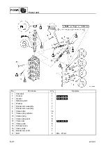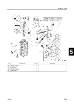
6C13G11
5-16
1
2
3
4
5
6
7
8
9
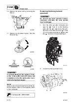
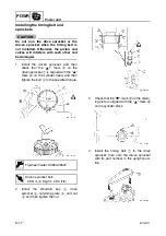
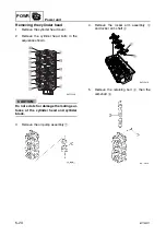
NOTE:
• Use a deep socket
2
for this procedure.
• Make sure that the camshaft does not turn
when loosening the drive sprocket nut.
3.
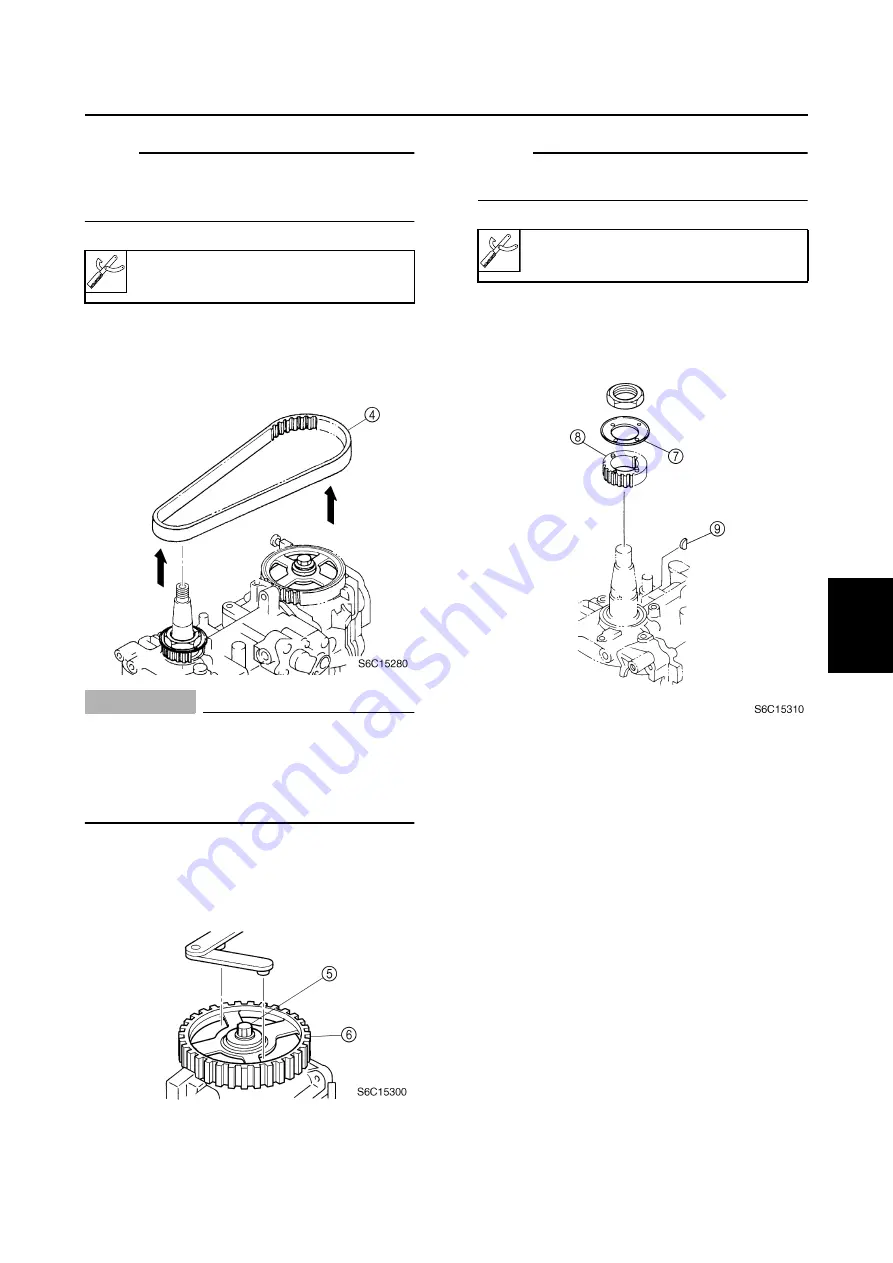
Remove the timing belt
4
from the
driven sprocket, then from the drive
sprocket.
CAUTION:
Do not turn the drive sprocket or the
driven sprocket when the timing belt is
not installed. Otherwise the piston and
valves will interfere with each other and
be damaged.
4.
Loosen the driven sprocket bolt
5
and
remove the driven sprocket
6
.
NOTE:
Make sure that the camshaft does not crank
when loosening the driven sprocket bolt.
5.
Remove the nut, retaining plate
7
, drive
sprocket
8
, and Woodruff key
9
.
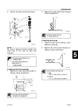
Checking the timing belt and
sprockets
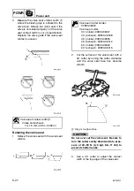
1.
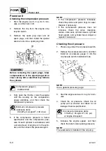
Check the interior and exterior of the tim-
ing belt for cracks, damage, or wear.
Replace if necessary.
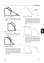
2.
Check the drive sprocket and driven
sprocket for cracks, damage, or wear.
Replace if necessary.
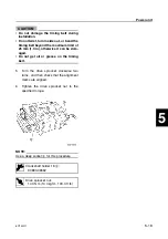
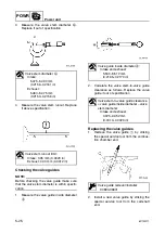
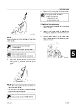
Crankshaft holder 18
3
:
90890-06562
Flywheel holder: 90890-06522
Summary of Contents for F50F
Page 1: ...F50F FT50G F60C FT60D SERVICE MANUAL 6C1 28197 3G 11 290551 ...
Page 4: ......
Page 48: ...SPEC Specifications 2 25 6C13G11 MEMO ...
Page 190: ...LOWR Lower unit 6 47 6C13G11 Shimming FT50 FT60 6 ...
Page 195: ...6C13G11 6 52 1 2 3 4 5 6 7 8 9 MEMO Backlash FT50 FT60 ...
Page 221: ...6C13G11 7 24 1 2 3 4 5 6 7 8 9 Steering arm ...
Page 249: ...6C13G11 7 52 1 2 3 4 5 6 7 8 9 MEMO Power trim and tilt electrical system ...
Page 272: ...ELEC Electrical systems 8 21 6C13G11 MEMO ...
Page 301: ...6C13G11 i 5 1 2 3 4 5 6 7 8 9 Index MEMO ...
Page 303: ......
Page 304: ...YAMAHA MOTOR CO LTD Printed in the Netherlands Jul 2004 1 2 1 CR E_2 ...

