6C13G11
5-24
1
2
3
4
5
6
7
8
9
6.
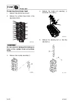
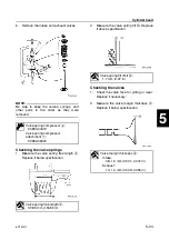
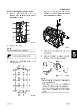
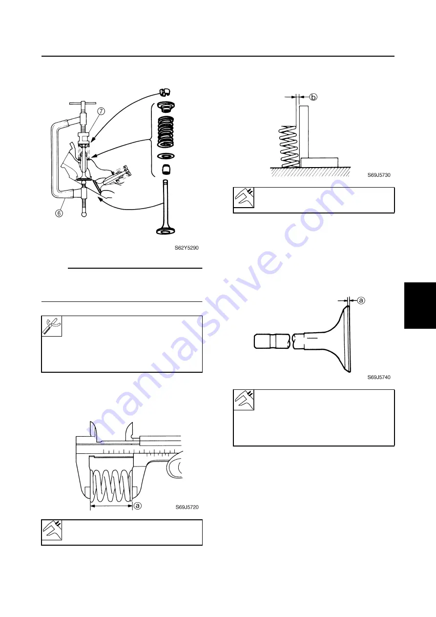
Remove the intake and exhaust valves.
NOTE:
Be sure to keep the valves, springs, and
other parts in the order as they were
removed.
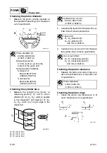
Checking the valve springs
1.
Measure the valve spring free length
a
.
Replace if below specification.
2.
Measure the valve spring tilt
b
. Replace
if above specification.
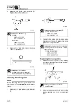
Checking the valves
1.
Check the valve face for pitting or wear.
Replace if necessary.
2.
Measure the valve margin thickness
a
.
Replace if below specification.
Valve spring compressor
6
:
90890-04019
Valve spring compressor
attachment
7
:
90890-06320
Valve spring free length
a
:
39.85 mm (1.5689 in)
Valve spring tilt limit
b
:
1.7 mm (0.07 in)
Valve margin thickness
a
:
Intake:
0.8–1.2 mm (0.031–0.047 in)
Exhaust:
1.0–1.4 mm (0.039–0.055 in)
Summary of Contents for F50F
Page 1: ...F50F FT50G F60C FT60D SERVICE MANUAL 6C1 28197 3G 11 290551 ...
Page 4: ......
Page 48: ...SPEC Specifications 2 25 6C13G11 MEMO ...
Page 190: ...LOWR Lower unit 6 47 6C13G11 Shimming FT50 FT60 6 ...
Page 195: ...6C13G11 6 52 1 2 3 4 5 6 7 8 9 MEMO Backlash FT50 FT60 ...
Page 221: ...6C13G11 7 24 1 2 3 4 5 6 7 8 9 Steering arm ...
Page 249: ...6C13G11 7 52 1 2 3 4 5 6 7 8 9 MEMO Power trim and tilt electrical system ...
Page 272: ...ELEC Electrical systems 8 21 6C13G11 MEMO ...
Page 301: ...6C13G11 i 5 1 2 3 4 5 6 7 8 9 Index MEMO ...
Page 303: ......
Page 304: ...YAMAHA MOTOR CO LTD Printed in the Netherlands Jul 2004 1 2 1 CR E_2 ...

