POWR
Power unit
5-25
6C13G11
3.
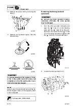
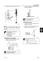
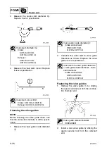
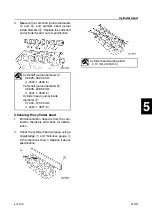
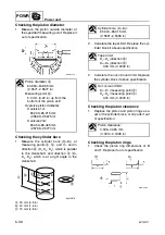
Measure the valve stem diameter
b
.
Replace if out of specification.
4.
Measure the valve stem runout. Replace
if above specification.
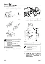
Checking the valve guides
NOTE:
Before checking the valve guide make sure
that the valve stem diameter is within specifi-
cation.
1.
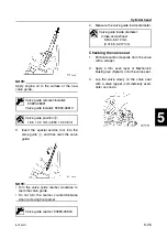
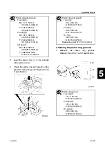
Measure the valve guide inside diameter
a
.
2.
Calculate the valve stem-to-valve guide
clearance as follows. Replace the valve
guide if out of specification.
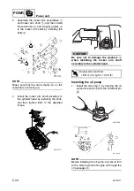
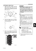
Replacing the valve guides
1.
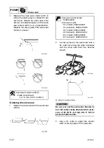
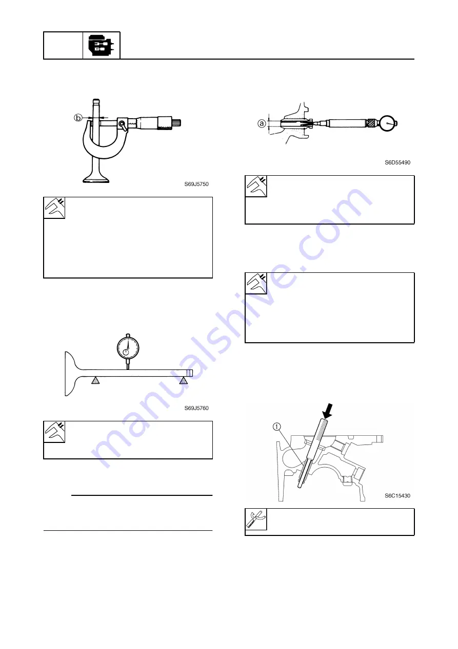
Remove the valve guide
1
by striking
the special service tool from the combus-
tion chamber end.
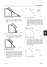
2.
Install a new valve guide by striking the
special service tool from the camshaft
end.
Valve stem diameter
b
:
Intake:
5.475–5.490 mm
(0.2156–0.2161 in)
Exhaust:
5.460–5.475 mm
(0.2150–0.2156 in)
Valve stem runout limit:
Intake: 0.05 mm (0.0020 in)
Exhaust: 0.03 mm (0.0012 in)
Valve guide inside diameter
a
:
Intake and exhaust:
5.500–5.512 mm
(0.2165–0.2170 in)
Valve stem-to-valve guide clearance
= valve guide inside diameter – valve
stem diameter:
Intake and exhaust:
0.025–0.052 mm
(0.0010–0.0020 in)
Valve guide remover/installer:
90890-06801
Summary of Contents for F50F
Page 1: ...F50F FT50G F60C FT60D SERVICE MANUAL 6C1 28197 3G 11 290551 ...
Page 4: ......
Page 48: ...SPEC Specifications 2 25 6C13G11 MEMO ...
Page 190: ...LOWR Lower unit 6 47 6C13G11 Shimming FT50 FT60 6 ...
Page 195: ...6C13G11 6 52 1 2 3 4 5 6 7 8 9 MEMO Backlash FT50 FT60 ...
Page 221: ...6C13G11 7 24 1 2 3 4 5 6 7 8 9 Steering arm ...
Page 249: ...6C13G11 7 52 1 2 3 4 5 6 7 8 9 MEMO Power trim and tilt electrical system ...
Page 272: ...ELEC Electrical systems 8 21 6C13G11 MEMO ...
Page 301: ...6C13G11 i 5 1 2 3 4 5 6 7 8 9 Index MEMO ...
Page 303: ......
Page 304: ...YAMAHA MOTOR CO LTD Printed in the Netherlands Jul 2004 1 2 1 CR E_2 ...

