BRKT
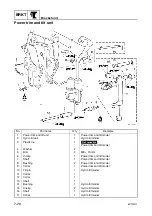
Bracket unit
7-33
6C13G11
3.
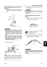
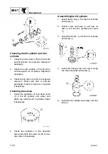
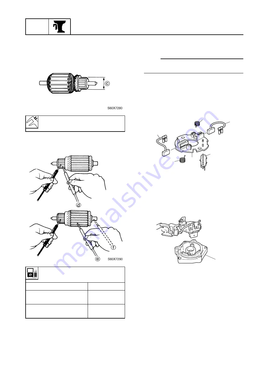
Measure the commutator diameter.
Replace if below specification.
4.
Check the armature for continuity.
Replace if out of specifications.
5.
Check the base for cracks or damage.
Replace if necessary.
6.
Check the bearings and oil seal for dam-
age or wear. Replace if necessary.
NOTE:
If the bearings and oil seal are removed,
always replace them with new ones.
Assembling the power trim and tilt
motor
1.
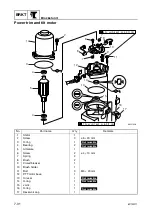
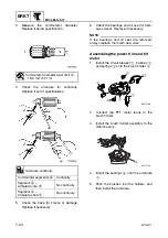
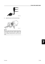
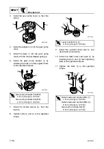
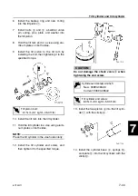
Install the circuit breaker
1
, brushes
2
,
and springs
3
onto the brush holder
4
.
2.
Connect the PTT motor leads to the
brush holder.
3.
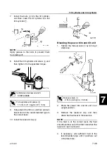
Install the brush holder assembly to the
motor base
5
.
4.
Install the bearings
6
onto the armature
7
.
5.
Push the brushes into the holders, and
then install the armature.
Commutator diameter wear limit
c
:
18.0 mm (0.71 in)
Armature continuity
Commutator segments
d
Continuity
Segment
d
–
Armature core
e
No continuity
Segment
d
–
Armature shaft
f
No continuity
S6C17500
2
3
3
4
1
2
S6C17510
5
Summary of Contents for F50F
Page 1: ...F50F FT50G F60C FT60D SERVICE MANUAL 6C1 28197 3G 11 290551 ...
Page 4: ......
Page 48: ...SPEC Specifications 2 25 6C13G11 MEMO ...
Page 190: ...LOWR Lower unit 6 47 6C13G11 Shimming FT50 FT60 6 ...
Page 195: ...6C13G11 6 52 1 2 3 4 5 6 7 8 9 MEMO Backlash FT50 FT60 ...
Page 221: ...6C13G11 7 24 1 2 3 4 5 6 7 8 9 Steering arm ...
Page 249: ...6C13G11 7 52 1 2 3 4 5 6 7 8 9 MEMO Power trim and tilt electrical system ...
Page 272: ...ELEC Electrical systems 8 21 6C13G11 MEMO ...
Page 301: ...6C13G11 i 5 1 2 3 4 5 6 7 8 9 Index MEMO ...
Page 303: ......
Page 304: ...YAMAHA MOTOR CO LTD Printed in the Netherlands Jul 2004 1 2 1 CR E_2 ...


