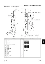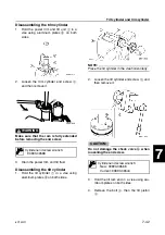
6C13G11
7-38
1
2
3
4
5
6
7
8
9
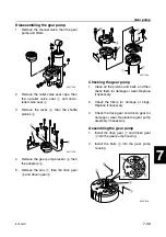
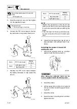
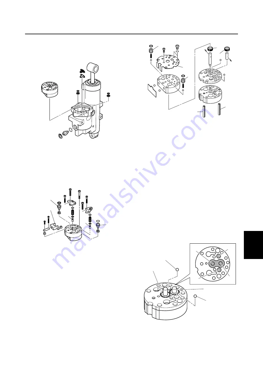
Disassembling the gear pump
1.
Remove the manual valve, then the gear
pump and filters.
2.
Remove the relief valve seat caps, then
the up-relief valve seat
1
and down-
relief valve seat
2
.
3.
Remove the lever
3
, then the shuttle
pistons
4
.
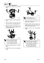
4.
Remove the gear pump bracket
5
, then
the adapters
6
.
5.
Remove the pins
7
, then the drive gear
8
and driven gear
9
.
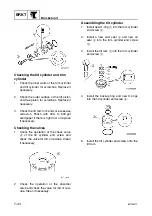
Checking the gear pump
1.
Clean all the pistons and balls, and then
check them for damage or wear. Replace
if necessary.
2.
Check the filters for damage or clogs.
Replace if necessary.
3.
Check the drive gear and driven gear for
damage or wear. Replace the gear pump
assembly if necessary.
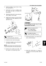
Assembling the gear pump
1.
Install the drive gear
1
and driven gear
2
into the gear pump housing.
2.
Install the balls
3
into the gear pump
housing.
S6C17580
4
3
2
1
4
S6C17590
S6C17600
6
6
5
7
7
8
9
S6C17610
1
2
3
3
1
2
3
3
Summary of Contents for F50F
Page 1: ...F50F FT50G F60C FT60D SERVICE MANUAL 6C1 28197 3G 11 290551 ...
Page 4: ......
Page 48: ...SPEC Specifications 2 25 6C13G11 MEMO ...
Page 190: ...LOWR Lower unit 6 47 6C13G11 Shimming FT50 FT60 6 ...
Page 195: ...6C13G11 6 52 1 2 3 4 5 6 7 8 9 MEMO Backlash FT50 FT60 ...
Page 221: ...6C13G11 7 24 1 2 3 4 5 6 7 8 9 Steering arm ...
Page 249: ...6C13G11 7 52 1 2 3 4 5 6 7 8 9 MEMO Power trim and tilt electrical system ...
Page 272: ...ELEC Electrical systems 8 21 6C13G11 MEMO ...
Page 301: ...6C13G11 i 5 1 2 3 4 5 6 7 8 9 Index MEMO ...
Page 303: ......
Page 304: ...YAMAHA MOTOR CO LTD Printed in the Netherlands Jul 2004 1 2 1 CR E_2 ...


