BRKT
Bracket unit
7-45
6C13G11
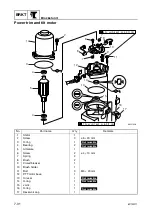
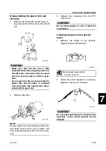
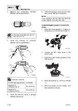
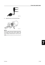
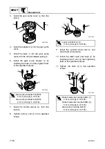
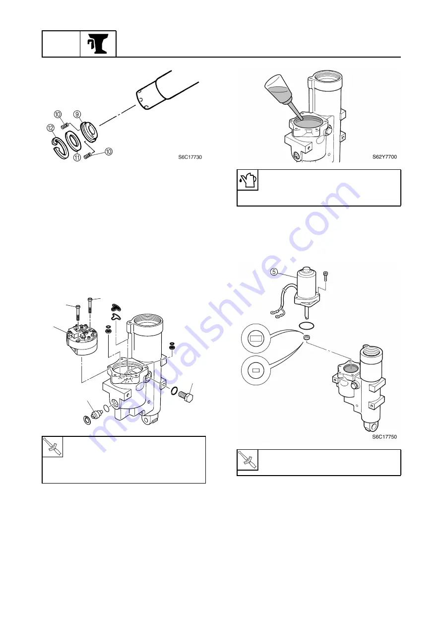
Assembling the power trim and tilt
unit
1.
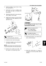
Hold the trim cylinder in a vise using alu-
minum plates on both sides.
2.
Install the filters and gear pump assem-
bly
1
by installing the bolts
2
, then tight-
ening them to the specified torque.
3.
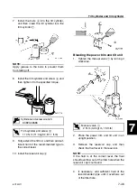
Install the manual valve
3
and reservoir
cap
4
.
4.
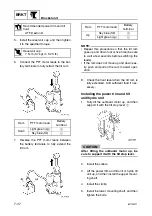
Fill the reservoir with the recommended
fluid to the correct level as shown.
5.
Install the new O-ring, joint, and power
trim and tilt motor
5
by installing the
bolts, then tightening them to the speci-
fied torque.
6.
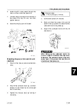
Add fluid of the recommended type to the
first level at the bottom of the trim cylin-
der.
T
R
.
.
Gear pump bolt
2
:
5 N·m (0.5 kgf·m, 3.7 ft·lb)
Reservoir cap
4
:
7 N·m (0.7 kgf·m, 5.2 ft·lb)
S6C17740
2
1
3
4
2
Recommended power trim and tilt
fluid:
ATF Dexron
II
T
R
.
.
PTT motor bolt:
4 N·m (0.4 kgf·m, 3.0 ft·lb)
Summary of Contents for F50F
Page 1: ...F50F FT50G F60C FT60D SERVICE MANUAL 6C1 28197 3G 11 290551 ...
Page 4: ......
Page 48: ...SPEC Specifications 2 25 6C13G11 MEMO ...
Page 190: ...LOWR Lower unit 6 47 6C13G11 Shimming FT50 FT60 6 ...
Page 195: ...6C13G11 6 52 1 2 3 4 5 6 7 8 9 MEMO Backlash FT50 FT60 ...
Page 221: ...6C13G11 7 24 1 2 3 4 5 6 7 8 9 Steering arm ...
Page 249: ...6C13G11 7 52 1 2 3 4 5 6 7 8 9 MEMO Power trim and tilt electrical system ...
Page 272: ...ELEC Electrical systems 8 21 6C13G11 MEMO ...
Page 301: ...6C13G11 i 5 1 2 3 4 5 6 7 8 9 Index MEMO ...
Page 303: ......
Page 304: ...YAMAHA MOTOR CO LTD Printed in the Netherlands Jul 2004 1 2 1 CR E_2 ...

