BRKT
Bracket unit
7-47
6C13G11
5.
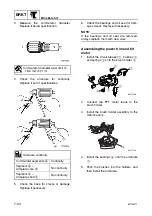
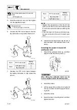
Install the reservoir cap, and then tighten
it to the specified torque.
6.
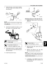
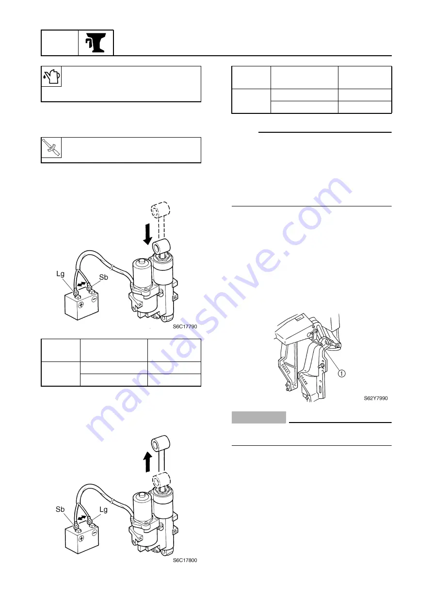
Connect the PTT motor leads to the bat-
tery terminals to fully retract the tilt ram.
7.
Reverse the PTT motor leads between
the battery terminals to fully extend the
tilt ram.
NOTE:
• Repeat this procedure so that the tilt ram
goes up and down four or five time (be sure
to wait a few seconds before switching the
leads).
• If the ram does not move up and down eas-
ily, push and pull on the ram to assist oper-
ation.
8.
Check the fluid level when the tilt ram is
fully extended. Add sufficient fluid if nec-
essary.
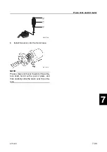
Installing the power trim and tilt
unit/hydro unit
1.
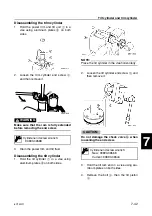
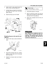
Fully tilt the outboard motor up, and then
support it with the tilt stop lever
1
.
CAUTION:
After tilting the outboard motor up, be
sure to support it with the tilt stop lever.
2.
Install the collars.
3.
Lift the power trim and tilt unit or hydro tilt
unit up, and then install the upper mount-
ing shaft.
4.
Install the circlip.
5.
Install the lower mounting shaft, and then
tighten the bolts.
Recommended power trim and tilt
fluid:
ATF Dexron
II
T
R
.
.
Reservoir cap:
7 N·m (0.7 kgf·m, 5.2 ft·lb)
Ram
PTT motor lead
Battery
terminal
Down
Light green (Lg)
+
Sky blue (Sb)
-
Ram
PTT motor lead
Battery
terminal
Up
Sky blue (Sb)
+
Light green (Lg)
-
Summary of Contents for F50F
Page 1: ...F50F FT50G F60C FT60D SERVICE MANUAL 6C1 28197 3G 11 290551 ...
Page 4: ......
Page 48: ...SPEC Specifications 2 25 6C13G11 MEMO ...
Page 190: ...LOWR Lower unit 6 47 6C13G11 Shimming FT50 FT60 6 ...
Page 195: ...6C13G11 6 52 1 2 3 4 5 6 7 8 9 MEMO Backlash FT50 FT60 ...
Page 221: ...6C13G11 7 24 1 2 3 4 5 6 7 8 9 Steering arm ...
Page 249: ...6C13G11 7 52 1 2 3 4 5 6 7 8 9 MEMO Power trim and tilt electrical system ...
Page 272: ...ELEC Electrical systems 8 21 6C13G11 MEMO ...
Page 301: ...6C13G11 i 5 1 2 3 4 5 6 7 8 9 Index MEMO ...
Page 303: ......
Page 304: ...YAMAHA MOTOR CO LTD Printed in the Netherlands Jul 2004 1 2 1 CR E_2 ...

