POWR
Power unit
5-3
6C13G11
Power unit
5
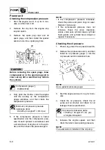
Checking the compression pressure
1.
Start the engine, warm it up for 5 min-
utes, and then turn it off.
2.
Remove the clip from the engine stop
lanyard switch.
3.
Remove the spark plug caps and all
spark plugs, and then install the special
service tools into a spark plug hole.
CAUTION:
Before removing the spark plugs, blow
compressed air in the spark plug well to
clear out any dirt or dust that may fall into
the cylinder.
4.
Fully open the throttle, crank the engine
until the reading on the compression
gauge stabilizes, and then check the
compression pressure.
5.
If the compression pressure is below
specification and the compression pres-
sure for each cylinder is unbalanced, add
a small amount of engine oil to the cylin-
der, and then check the pressure again.
NOTE:
• If the compression pressure increases,
check the pistons and piston rings for wear.
Replace if necessary.
• If the compression pressure does not
increase, check the valve clearance,
valves, valve seat, cylinder sleeve, cylinder
head gasket, and cylinder head. Adjust or
replace if necessary.
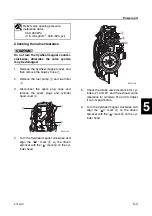
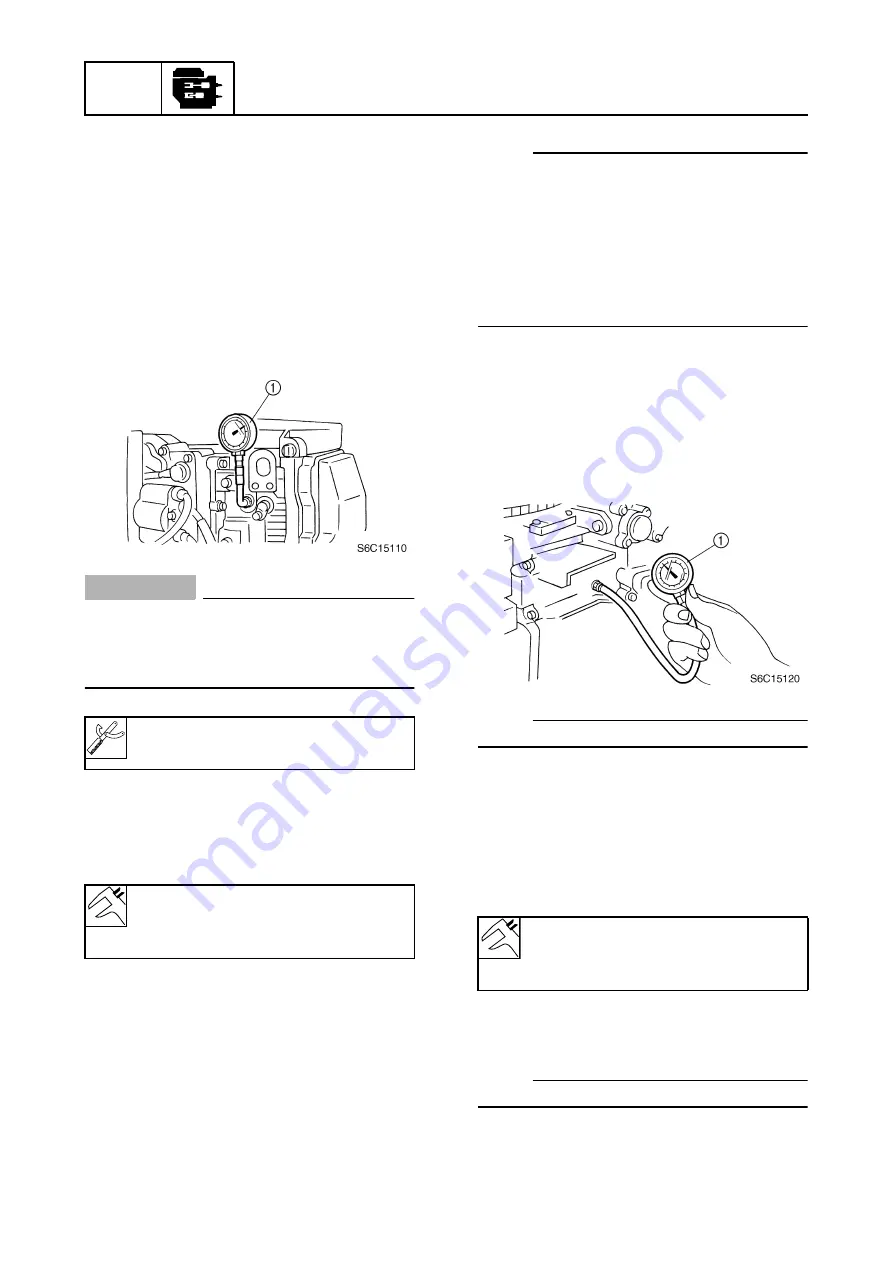
Checking the oil pressure
1.
Place a rag under the oil pressure switch.
2.
Remove the oil pressure switch, and then
install an oil pressure gauge
1
into the
oil pressure switch installation hole.
NOTE:
Use a general pressure gauge.
3.
Start the engine and warm it up for 5 min-
utes.
4.
Check the oil pressure. Check the oil
pump and oil strainer and check for oil
leakage if below specification.
5.
Increase the engine speed, and then
check the relief valve opening pressure.
NOTE:
The relief valve is installed in the oil pump.
Compression gauge
1
:
90890-03160
Minimum compression pressure
(reference data):
960 kPa (9.6 kgf/cm
2
, 139.2 psi)
Oil pressure (reference data):
125 kPa (1.25 kgf/cm
2
, 18.1 psi)
at engine idle speed
Summary of Contents for F50F
Page 1: ...F50F FT50G F60C FT60D SERVICE MANUAL 6C1 28197 3G 11 290551 ...
Page 4: ......
Page 48: ...SPEC Specifications 2 25 6C13G11 MEMO ...
Page 190: ...LOWR Lower unit 6 47 6C13G11 Shimming FT50 FT60 6 ...
Page 195: ...6C13G11 6 52 1 2 3 4 5 6 7 8 9 MEMO Backlash FT50 FT60 ...
Page 221: ...6C13G11 7 24 1 2 3 4 5 6 7 8 9 Steering arm ...
Page 249: ...6C13G11 7 52 1 2 3 4 5 6 7 8 9 MEMO Power trim and tilt electrical system ...
Page 272: ...ELEC Electrical systems 8 21 6C13G11 MEMO ...
Page 301: ...6C13G11 i 5 1 2 3 4 5 6 7 8 9 Index MEMO ...
Page 303: ......
Page 304: ...YAMAHA MOTOR CO LTD Printed in the Netherlands Jul 2004 1 2 1 CR E_2 ...

