Operation
22
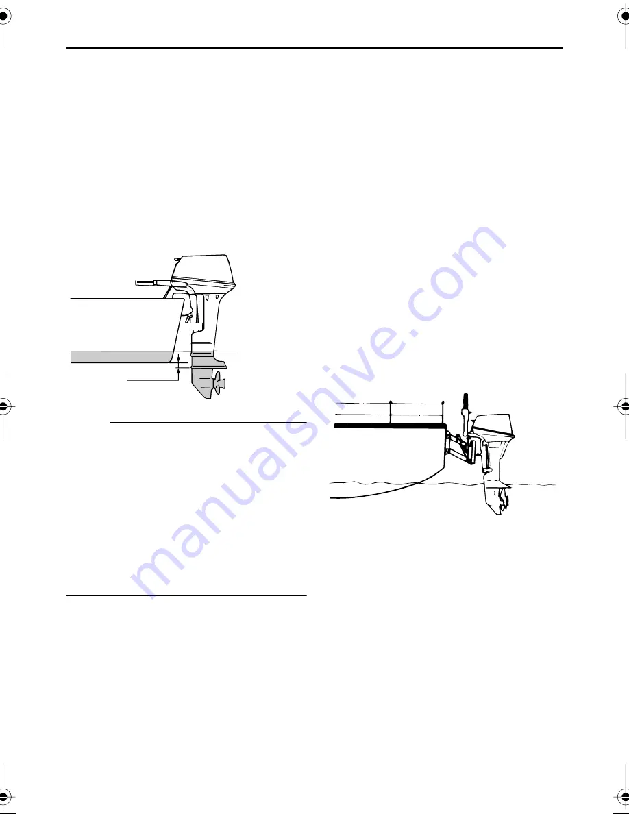
motor greatly affects the water resistance. If
the mounting height is too high, cavitation
tends to occur, thus reducing the propulsion;
and if the propeller tips cut the air, the engine
speed will rise abnormally and cause the en-
gine to overheat. If the mounting height is too
low, the water resistance will increase and
thereby reduce engine efficiency. Mount the
outboard motor so that the anti-cavitation
plate is between the bottom of the boat and
a level 25 mm (1 in.) below it.
NOTE:
●
The optimum mounting height of the out-
board motor is affected by the boat and
motor combination and the desired use.
Test runs at different heights can help de-
termine the optimum mounting height.
Consult your Yamaha dealer or boat man-
ufacturer for further information on deter-
mining the proper mounting height.
●
For instructions on setting the trim angle of
the outboard motor, see page 34.
EMU26960
Mounting height for sailboat
When mounting the outboard motor on the
motor bracket of a sailboat, check the follow-
ing points:
●
When using the outboard motor, the cavi-
tation plate should be 50 mm (2 in.) or
more below the water surface to prevent
propeller damage. Because a sailboat can
pitch considerably, mount the outboard
motor low enough so that the propeller will
not contact the water surface during mo-
tor-powered operation.
●
When sailing, the outboard motor should
be able to be tilted up out of the water so
the propeller does not contact the water
spray. Disconnect the fuel line.
●
Check that the outboard motor does not in-
terfere with the rudder.
●
Check that the engine can be easily start-
ed and stopped.
●
Check the ease of operating the gear shift
and throttle control.
●
If mounting the outboard motor on a well-
type boat, exhaust gases and blow-by gas
flow must be allowed to exit the boat. A
special kit designed for this purpose can
be ordered through your Yamaha dealer.
EMU26970
Clamping the outboard motor
1.
Place the outboard motor on the tran-
som so that it is positioned as close to
the center as possible. Tighten the tran-
som clamp screws evenly and securely.
Occasionally check the clamp screws
for tightness during operation of the out-
board motor because they could be-
ZMU02011
0–25mm
(0–1in.)
ZMU04376
Summary of Contents for F9.9D
Page 1: ...F9 9D T9 9D OWNER S MANUAL 6G8 28199 1N U S A Edition LIT 18626 06 00 ...
Page 2: ...EMU25060 ZMU01690 Read this owner s manual carefully before operating your outboard motor ...
Page 74: ...69 Consumer information EMU29811 Important warranty information for U S A and Canada ...
Page 75: ...Consumer information 70 ...
Page 77: ...Consumer information 72 ...
Page 79: ...Printed in Japan April 2004 0 4 1 Printed on recycled paper ...
Page 81: ...PLACE POSTAGE HERE ATTN WARRANTY DEPARTMENT Warranty card 2 27 02 11 47 AM Page 2 ...


