background image

EAS00002 

NOTICE

This manual was produced by the Yamaha Motor Company, Ltd. primarily for use by Yamaha deal-
ers and their qualified mechanics. It is not possible to include all the knowledge of a mechanic in
one manual. Therefore, anyone who uses this book to perform maintenance and repairs on Yamaha
vehicles should have a basic understanding of mechanics and the techniques to repair these types
of vehicles. Repair and maintenance work attempted by anyone without this knowledge is likely to
render the vehicle unsafe and unfit for use.

Yamaha Motor Company, Ltd. is continually striving to improve all of its models. Modifications and
significant changes in specifications or procedures will be forwarded to all authorized Yamaha deal-
ers and will appear in future editions of this manual where applicable.

NOTE:

Designs and specifications are subject to change without notice. 

EAS00004

IMPORTANT MANUAL INFORMATION

Particularly important information is distinguished in this manual by the following.

The Safety Alert Symbol means ATTENTION! BECOME ALERT! YOUR
SAFETY IS INVOLVED!

Failure to follow WARNING instructions could result in severe injury or death to
the motorcycle operator, a bystander or a person checking or repairing the
motorcycle.

A CAUTION indicates special precautions that must be taken to avoid damage
to the motorcycle.

A NOTE provides key information to make procedures easier or clearer.

WARNING

CAUTION:

NOTE:

Summary of Contents for FJR1300(S)

Page 1: ...2004 FJR1300 S FJR1300A S 5JW1 AE5 SUPPLEMENTARY SERVICE MANUAL...

Page 2: ......

Page 3: ...ther with the following manuals FJR1300 N 2001 SERVICE MANUAL 5JW1 AE1 FJR1300 P 2002 SUPPLEMENTARY SERVICE MANUAL 5JW1 AE2 FJR1300 R FJR1300A R 2003 SUPPLEMENTARY SERVICE MANUAL 5JW1 AE4 FJR1300 S FJ...

Page 4: ...ls Modifications and significant changes in specifications or procedures will be forwarded to all authorized Yamaha deal ers and will appear in future editions of this manual where applicable NOTE Des...

Page 5: ...f each page except in chapter 3 PERIODIC CHECKS AND ADJUSTMENTS where the sub section title s appears 3 Sub section titles appear in smaller print than the section title 4 To help identify parts and c...

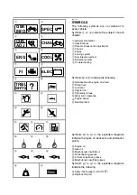
Page 6: ...fluid B Lubricant C Special tool D Tightening torque E Wear limit clearance F Engine speed G Electrical data Symbols H to M in the exploded diagrams indicate the types of lubricants and lubrication p...

Page 7: ...NK 7 REMOVING THE FUEL TANK 9 AIR FILTER CASE 10 FUEL INJECTION SYSTEM 12 FUEL INJECTION SYSTEM 12 WIRING DIAGRAM FJR1300 13 WIRING DIAGRAM FJR1300A 14 SUBSTITUTE CHARACTERISTICS OPERATION CONTROL FAI...

Page 8: ......

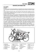
Page 9: ...ol the air fuel ratio in a more precise and finely tuned man ner To accommodate this need this model has adopted an electronically controlled fuel injection FI system in place of the conventional carb...

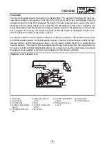
Page 10: ...duration and the injection timing are controlled by the ECU Signals that are input from the throttle position sensor crankshaft position sensor intake air pressure sensor intake air tem perature senso...

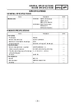
Page 11: ...e Electric Model manufacturer 5JW 21 DENSO Maximum consumption amperage 6 0 A Output pressure 324 kPa 3 24 kg cm2 46 08 psi Throttle bodies Model manufacturer quantity 42EHS MIKUNI 4 Intake vacuum pre...

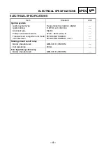
Page 12: ...l Ignition timing 5 BTDC at 1 050 r min Advancer type Electric Pickup coil resistance color 420 8 569 3 Gy B Transistorized coil ignition unit model manufacturer F8T818 MITSUBISHI F8T819 MITSUBISHI fo...

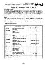
Page 13: ...TENANCE JOB ODOMETER READING 1 000 km ANNUAL CHECK 1 10 20 30 40 1 Fuel line Check fuel hoses for cracks or damage 2 Spark plugs Check condition Clean and regap Replace 3 Valves Check valve clearance...

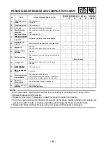
Page 14: ...age 19 Rear suspension relay arm and con necting arm pivot ing points Check operation Lubricate with lithium soap based grease 20 Electronic fuel injection Adjust engine idling speed and synchronizati...

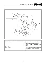
Page 15: ...k Remove the parts in the order listed Rider seat Refer to SEATS AND FUEL TANK in chapter 3 Manual No 5JW1 AE1 Fuel Drain 1 Fuel tank side panel left and right 1 1 2 Bolt 2 3 Nut 1 4 Fuel sender coupl...

Page 16: ...ob Part Q ty Remarks 10 Fuel hose 1 Refer to REMOVING THE FUEL TANK Refer to INSTALLING THE FUEL HOSE in chapter 3 Manual No 5JW1 AE1 11 Bolt 1 12 Fuel tank 1 Refer to REMOVING THE FUEL TANK For insta...

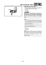
Page 17: ...be fuel remaining in it NOTE To remove the fuel hose from the fuel injec tion pipe slide the cover a on the end of the hose in the direction of the arrow shown and then remove the hose Before removing...

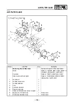
Page 18: ...No 5JW1 AE1 Fuel tank Refer to SEATS AND FUEL TANK Side covers left and right Refer to COWLINGS AND COVERS Manual No 5JW1 AE2 1 Air shroud 1 2 Air filter case cover 1 3 Air filter element 1 4 Tray 1...

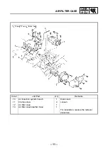
Page 19: ...rder Job Part Q ty Remarks 10 Air induction system hose 5 1 Disconnect 11 Clamp screw 4 Loosen 12 Air filter case 1 13 Air filter case breather hose 1 For installation reverse the removal procedure AI...

Page 20: ...mp 7 Intake air pressure sensor 8 Throttle position sensor 9 Fuel injector 0 O2 sensor A Catalytic converter B Crankshaft position sensor C Coolant temperature sensor D Spark plug E Cylinder identific...

Page 21: ...Y R L L B L B L B R L L B D GRAY R L G B G B G B R LG B D GRAY R L R B R B R B R L R B D GRAY R B R G B2 Br R R W G W Y L G L Lg Y L Ch W Dg BLACK BLUE BLUE BLUE L G B B B BB1 BB2 BB4 BB3 B B B B R W...

Page 22: ...R W R B L W G Y Br B R W R B W L G Y Br B B W R L B R L Y Br W L W B1 Lg Sb B2 W1 G R Lg Sb B1 B2 W1 G R R G R W R B W W R R Y Br W L W L B Br G C B L P W Gy G Y W B B L P W W B Y Gy G E BLACK BLACK B...

Page 23: ...ed Able Able 32 The amount of air fuel ratio feed back compensation is maintained continuously in the vicinity of the lower limit rich air fuel ratio Able Able 14 Faulty intake air pressure sensor pip...

Page 24: ...identification that existed up to that point Able Able 12 Crankshaft position sen sor Stops the engine by stopping the injection and ignition Unable Unable 13 14 Intake air pressure sensor open or sh...

Page 25: ...ir pressure sensor Malfunction in ECU 03 Or a stuck throttle position sensor is detected Open or short circuit in wiring sub lead Open or short circuit in wiring harness Defective sensor stuck throttl...

Page 26: ...of ignition cutoff circuit system 30 34 Open circuit is detected in the primary wire of the ignition coil 2 3 Open or short circuit in wiring harness Malfunction in ignition coil Malfunction in ECU M...

Page 27: ...if the numbers appear on the meter 08 Lean angle cut off switch Displays the lean angle cut off switch values Upright 0 4 1 4 V Overturned 3 8 4 2 V 09 Fuel system voltage battery voltage Displays the...

Page 28: ...ctive Refer to CHECKING THE SWITCHES in chapter 8 Manual No 5JW1 AE1 If the transmission is in gear it is rein stated by retracting the sidestand If the transmission is in neutral it is reinstated by...

Page 29: ...TS AND FUEL TANK in chapter 3 Manual No 5JW1 AE1 Fuel tank Refer to SEATS AND FUEL TANK Air filter case Refer to AIR FILTER CASE Coolant Drain Refer to CHANGING THE COOLANT in chapter 3 Manual No 5JW1...

Page 30: ...5 5 5 10 10 3 7 7 6 10 10 Order Job Part Q ty Remarks 7 Throttle cable 2 Disconnect 8 Plunger control unit hose 1 1 Disconnect 9 Plunger control unit hose 2 1 Disconnect 10 Throttle body joint 4 For i...

Page 31: ...ition sensor coupler 1 Disconnect 2 Intake air pressure sensor coupler 1 Disconnect 3 Cylinder 1 injector coupler 1 Disconnect 4 Cylinder 2 injector coupler 1 Disconnect 5 Cylinder 3 injector coupler...

Page 32: ...SYSTEM 11 3 4 5 6 1 7 2 8 12 13 14 10 10 10 9 Order Job Part Q ty Remarks 11 Intake air pressure sensor 1 12 Fuel injection pipe 1 13 Injector 4 14 Throttle position sensor 1 For installation reverse...

Page 33: ...AIR INDUCTION SYSTEM AIR INDUCTION SYSTEM INSTALLING THE REED VALVES 1 Install plate 1 NOTE Align the notch a in each plate with the pro jection b of each reed valve seat on the cylin der head cover...

Page 34: ...unit 2 Battery 3 Starter relay 4 Fuel injection system fuse 5 Front brake light switch 6 Clutch switch 7 Fuse box 8 Radiator fan motor 9 Wire harness 0 Neutral switch A Sidestand switch B Oil level sw...

Page 35: ...Lean angle cut off switch 6 Hydraulic unit FJR1300A 7 Fail safe relay FJR1300A 8 ECU engine 9 ECU ABS FJR1300A 0 Speed sensor A Cylinder identification sensor B O2 sensor C Crankshaft position sensor...

Page 36: ...W Br Br R GRAY R L L B L B L B R L L B D GRAY R L G B G B G B R LG B D GRAY R L R B R B R B R L R B D GRAY R B R G B2 Br R R W G W Y L G L Lg Y L Ch W Dg BLACK BLUE BLUE BLUE L G B B B BB1 BB2 BB4 BB3...

Page 37: ...R W R B L W G Y Br B R W R B W L G Y Br B B W R L B R L Y Br W L W B1 Lg Sb B2 W1 G R Lg Sb B1 B2 W1 G R R G R W R B W W R R Y Br W L W L B Br G C B L P W Gy G Y W B B L P W W B Y Gy G E BLACK BLACK...

Page 38: ...identally spill gasoline wipe it up immediately with dry rags If gasoline touches the engine when it is hot a fire may occur Therefore make sure the engine is completely cool before performing the fol...

Page 39: ...switch k Dimmer switch l Windshield position switch m Turn signal switch n Horn switch o Horn p Front turn signal light left q Front turn signal light right r Hazard switch s Headlight relay 1 t Headl...

Page 40: ...al indicator light p Meter light q Oil level switch r Left handlebar switch s Clutch switch t Pass switch u Dimmer switch v Windshield position switch w Turn signal switch x Horn switch y Horn z Front...

Page 41: ......

Page 42: ...YAMAHA MOTOR CO LTD 2500 SHINGAI IWATA SHIZUOKA JAPAN...

Page 43: ...O L R L R L D B L B L E W L B1 BB B2 B2 B L W B W B W B E P W P W B L Gy B L Y L B L Gy G Gy G Gy G W L Y B L L W B B L W L Y B L L W Y B L L Y B L BLACK DARK GREEN L B L P W P W B L L BLACK L O W B B...

Page 44: ...G B L Br R R W Br Br R GRAY R L L B L B L B R L L B D GRAY R L G B G B G B R LG B D GRAY R L R B R B R B R LR B D GRAY R B R G B2 Br R R W G W Y L G L G R Lg Y L Ch W Dg BLACK BLUE BLUE BLUE L G B B B...

Reviews: