3 - 55
CHK
ADJ
ADJUSTING THE REAR BRAKE LIGHT SWITCH/
CHECKING THE BRAKE HOSES
1. Check:
• rear brake light operation timing
Incorrect
→
Adjust.
2. Adjust:
• rear brake light operation timing
▼▼▼
▼
▼ ▼▼▼
▼
▼ ▼▼▼
▼
▼ ▼▼▼
▼
▼ ▼▼▼
▼
▼ ▼▼▼
▼
▼▼▼
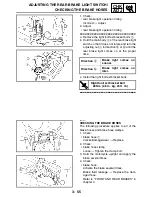
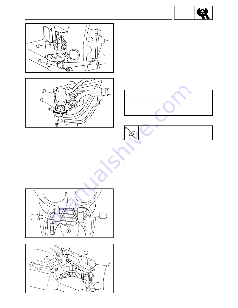
a. Remove the right footrest bracket bolts
1
.
b. Hold the main body
2
of the rear brake light
switch so that it does not rotate and turn the
adjusting nut
3
in direction
a
or
b
until the
rear brake light comes on at the proper
time.
c. Install the right footrest bracket bolts.
▲▲▲
▲
▲ ▲▲▲
▲
▲ ▲▲▲
▲
▲ ▲▲▲
▲
▲ ▲▲▲
▲
▲ ▲▲▲
▲
▲▲▲
Direction
a
Brake light comes on
sooner.
Direction
b
Brake light comes on
later.
T
R
.
.
Right footrest bracket bolt
28 Nm (2.8 m · kg, 20 ft · lb)
EAS00131
CHECKING THE BRAKE HOSES
The following procedure applies to all of the
brake hoses and brake hose clamps.
1. Check:
• brake hose
1
Cracks/damage/wear
→
Replace.
2. Check:
• brake hose clamp
Loose
→
Tighten the clamp bolt.
3. Hold the motorcycle upright and apply the
brake several times.
4. Check:
• brake hose
Activate the brake several times.
Brake fluid leakage
→
Replace the dam-
aged hose.
Refer to “FRONT AND REAR BRAKES” in
chapter 4.
Summary of Contents for FJR1300
Page 1: ...LIT 11616 16 18 5JW 28197 10 FJR1300R FJR1300RC SERVICE MANUAL ...
Page 6: ......
Page 82: ...2 22 SPEC TIGHTENING TORQUES Cylinder head tightening sequence Crankcase tightening sequence ...
Page 89: ...2 29 SPEC 1 Crankshaft 2 Main axle 3 Drive axle OIL FLOW DIAGRAMS ...
Page 90: ...2 30 SPEC 1 Oil nozzle 2 Main gallery bolt 3 Crankshaft OIL FLOW DIAGRAMS ...
Page 91: ...2 31 SPEC 1 Main axle 2 Drive axle 3 Oil delivery pipe OIL FLOW DIAGRAMS ...
Page 92: ...2 32 SPEC 1 Exhaust camshaft 2 Oil check bolt 3 Intake camshaft OIL FLOW DIAGRAMS ...
Page 94: ...2 34 SPEC 1 Crank pin 2 Crankshaft OIL FLOW DIAGRAMS ...
Page 97: ...2 37 SPEC 1 Main axle 2 Drive axle 3 Middle drive shaft OIL FLOW DIAGRAMS ...
Page 98: ...2 38 SPEC COOLING SYSTEM DIAGRAMS 1 Radiator COOLING SYSTEM DIAGRAMS ...
Page 99: ...2 39 SPEC 1 Water jacket joint 2 Oil cooler COOLING SYSTEM DIAGRAMS ...
Page 101: ...2 41 SPEC 1 Coolant reservoir 2 Radiator 3 Water pump COOLING SYSTEM DIAGRAMS ...
Page 107: ...2 47 SPEC CABLE ROUTING 1 Tail brake light lead ...
Page 196: ...3 80 CHK ADJ ADJUSTING THE HEADLIGHT BEAMS ...
Page 288: ...4 92 CHAS 3 Install bearing 1 to the swingarm Installed depth a 4 0 mm 0 16 in SWINGARM ...
Page 531: ...8 35 ELEC LIGHTING SYSTEM ...
Page 570: ......
Page 571: ...YAMAHA MOTOR CO LTD 2500 SHINGAI IWATA SHIZUOKA JAPAN PRINTED IN U S A ...

