7 - 11
FI
FUEL INJECTION SYSTEM
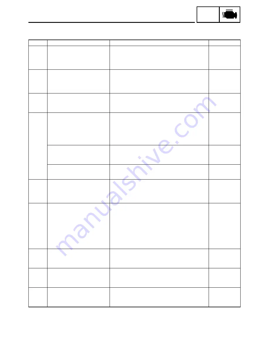
Self-diagnostic fault codes, symptoms, and probable causes
Diagnostic code indication
Code No.
Symptom
Probable cause of malfunction
Diagnostic code
11
No normal signals are received from
the cylinder identification sensor.
• Open or short circuit in wiring sub lead.
• Open or short circuit in wiring harness.
• Defective cylinder identification sensor.
• Malfunction in ECU.
• Improperly installed sensor.
—
12
No normal signals are received from
the crankshaft position sensor.
• Open or short circuit in wiring harness.
• Defective crankshaft position sensor.
• Malfunction in pickup rotor.
• Malfunction in ECU.
• Improperly installed sensor.
—
13
Intake air pressure sensor - open or
short circuit detected.
• Open or short circuit in wiring sub lead.
• Open or short circuit in wiring harness.
• Defective intake air pressure sensor.
• Malfunction in ECU.
03
14
Faulty intake air pressure sensor pipe
system; a hose is detached, causing
constant application of the atmo-
spheric pressure to the sensor; or, the
hose is clogged.
• Intake air pressure sensor hose is detached, clogged,
kinked, or pinched.
• Malfunction of the intake air pressure sensor in the interme-
diate electrical potential.
• Malfunction of the atmospheric pressure sensor in the inter-
mediate electrical potential.
• Malfunction in ECU.
03
02
Or, intake air pressure sensor - open
or short circuit detected.
• Open or short circuit in wiring sub lead.
• Open or short circuit in wiring harness.
• Defective intake air pressure sensor.
• Malfunction in ECU.
03
Or, a stuck throttle position sensor is
detected.
• Open or short circuit in wiring sub lead.
• Open or short circuit in wiring harness.
• Defective sensor (stuck throttle position sensor).
01
15
Throttle position sensor - open or
short circuit detected.
• Open or short circuit in wiring sub lead.
• Open or short circuit in wiring harness.
• Defective throttle position sensor.
• Malfunction in ECU.
• Improperly installed throttle position sensor.
01
16
A stuck throttle position sensor is
detected.
Or,
Faulty intake air pressure sensor pipe
system; a hose is detached, causing
constant application of the atmo-
spheric pressure to the sensor; or, the
hose is clogged.
• Open or short circuit in wiring sub lead.
• Open or short circuit in wiring harness.
• Defective sensor (stuck throttle position sensor).
• Intake air pressure sensor hose is detached, clogged,
kinked, or pinched.
• Malfunction of the intake air pressure sensor in the interme-
diate electrical potential.
• Malfunction of the atmospheric pressure sensor in the inter-
mediate electrical potential.
• Malfunction in ECU.
01
03
02
19
Open circuit in the input line from the
sidestand switch to the ECU is
detected when the start switch is
pressed.
• Open or short circuit in wiring harness.
• Malfunction in ECU.
20
21
Coolant temperature sensor - open or
short circuit detected.
• Open or short circuit in wiring harness.
• Defective coolant temperature sensor.
• Malfunction in ECU.
• Improperly installed sensor.
06
22
Intake temperature sensor - open or
short circuit detected.
• Open or short circuit in wiring harness.
• Defective intake temperature sensor.
• Malfunction in ECU.
• Improperly installed sensor.
05
Summary of Contents for FJR1300
Page 1: ...LIT 11616 16 18 5JW 28197 10 FJR1300R FJR1300RC SERVICE MANUAL ...
Page 6: ......
Page 82: ...2 22 SPEC TIGHTENING TORQUES Cylinder head tightening sequence Crankcase tightening sequence ...
Page 89: ...2 29 SPEC 1 Crankshaft 2 Main axle 3 Drive axle OIL FLOW DIAGRAMS ...
Page 90: ...2 30 SPEC 1 Oil nozzle 2 Main gallery bolt 3 Crankshaft OIL FLOW DIAGRAMS ...
Page 91: ...2 31 SPEC 1 Main axle 2 Drive axle 3 Oil delivery pipe OIL FLOW DIAGRAMS ...
Page 92: ...2 32 SPEC 1 Exhaust camshaft 2 Oil check bolt 3 Intake camshaft OIL FLOW DIAGRAMS ...
Page 94: ...2 34 SPEC 1 Crank pin 2 Crankshaft OIL FLOW DIAGRAMS ...
Page 97: ...2 37 SPEC 1 Main axle 2 Drive axle 3 Middle drive shaft OIL FLOW DIAGRAMS ...
Page 98: ...2 38 SPEC COOLING SYSTEM DIAGRAMS 1 Radiator COOLING SYSTEM DIAGRAMS ...
Page 99: ...2 39 SPEC 1 Water jacket joint 2 Oil cooler COOLING SYSTEM DIAGRAMS ...
Page 101: ...2 41 SPEC 1 Coolant reservoir 2 Radiator 3 Water pump COOLING SYSTEM DIAGRAMS ...
Page 107: ...2 47 SPEC CABLE ROUTING 1 Tail brake light lead ...
Page 196: ...3 80 CHK ADJ ADJUSTING THE HEADLIGHT BEAMS ...
Page 288: ...4 92 CHAS 3 Install bearing 1 to the swingarm Installed depth a 4 0 mm 0 16 in SWINGARM ...
Page 531: ...8 35 ELEC LIGHTING SYSTEM ...
Page 570: ......
Page 571: ...YAMAHA MOTOR CO LTD 2500 SHINGAI IWATA SHIZUOKA JAPAN PRINTED IN U S A ...

