FRONT WHEEL
4-19
EAS21900
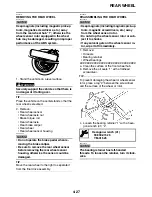
REMOVING THE FRONT WHEEL
NOTICE
ECA3P6D002
Keep magnets (including magnetic pick-up
tools, magnetic screwdrivers, etc.) away
from the front wheel hub “1”, otherwise the
wheel sensor rotor equipped in the wheel
hub may be damaged, resulting in improper
performance of the ABS system.
1. Stand the vehicle on a level surface.
WARNING
EWA13120
Securely support the vehicle so that there is
no danger of it falling over.
2. Remove:
• Front wheel sensor
• Front brake calipers
NOTICE
ECA3P6D015
Do not operate the brake lever and brake
pedal when removing the brake calipers.
3. Elevate:
• Front wheel
TIP
Place the vehicle on a suitable stand so that the
front wheel is elevated.
EAS21910
DISASSEMBLING THE FRONT WHEEL
NOTICE
ECA3P6D003
• Keep magnets (including magnetic pick-up
tools, magnetic screwdrivers, etc.) away
from the wheel sensor rotor.
• Do not drop the wheel sensor rotor or sub-
ject it to shocks.
• If any solvent gets on the wheel sensor ro-
tor, wipe it off immediately.
1. Remove:
• Oil seals
• Wheel bearings
▼▼▼
▼
▼ ▼▼▼
▼
▼ ▼▼▼
▼
▼ ▼▼▼
▼
▼ ▼▼▼
▼
▼ ▼▼▼
▼
▼▼▼
a. Clean the surface of the front wheel hub.
b. Remove the oil seals “1” with a flathead
screwdriver.
TIP
To prevent damaging the wheel or wheel sensor
rotor, place a rag “2” between the screwdriver
and the surface of the wheel or rotor.
c. Remove the wheel sensor rotor.
d. Remove the wheel bearings “3” with a gener-
al bearing puller.
▲▲▲
▲
▲ ▲▲▲
▲
▲ ▲▲▲
▲
▲ ▲▲▲
▲
▲ ▲▲▲
▲
▲ ▲▲▲
▲
▲▲▲
EAS21920
CHECKING THE FRONT WHEEL
1. Check:
• Wheel axle
Roll the wheel axle on a flat surface.
Bends
→
Replace.
WARNING
EWA13460
Do not attempt to straighten a bent wheel ax-
le.
1
Summary of Contents for FJR13AY 2009
Page 1: ...2009 SERVICE MANUAL FJR13AY C FJR13AEY C LIT 11616 22 73 3P6 28197 12 ...
Page 6: ......
Page 8: ......
Page 80: ...LUBRICATION SYSTEM CHART AND DIAGRAMS 2 31 EAS20410 LUBRICATION DIAGRAMS 5 6 7 1 2 3 4 ...
Page 82: ...LUBRICATION SYSTEM CHART AND DIAGRAMS 2 33 1 3 2 ...
Page 83: ...LUBRICATION SYSTEM CHART AND DIAGRAMS 2 34 1 Main axle 2 Drive axle 3 Oil delivery pipe 1 ...
Page 84: ...LUBRICATION SYSTEM CHART AND DIAGRAMS 2 35 6 5 4 3 2 1 ...
Page 86: ...LUBRICATION SYSTEM CHART AND DIAGRAMS 2 37 1 2 3 4 5 6 7 8 9 ...
Page 88: ...LUBRICATION SYSTEM CHART AND DIAGRAMS 2 39 4 5 3 2 1 9 8 6 7 ...
Page 92: ...COOLING SYSTEM DIAGRAMS 2 43 A A 7 1 2 3 4 5 5 7 8 6 8 9 10 11 12 ...
Page 98: ...CABLE ROUTING FJR13A 2 49 2 3 4 5 6 7 8 9 11 10 12 13 14 15 16 A B C D E F 1 1 ...
Page 100: ...CABLE ROUTING FJR13A 2 51 1 2 3 4 5 6 7 8 A B C D E 9 10 11 12 13 ...
Page 108: ...CABLE ROUTING FJR13A 2 59 1 2 3 4 A B B C D E ...
Page 110: ...CABLE ROUTING FJR13A 2 61 A 1 A A B P O C D E F G H I J K L M N 2 3 4 5 6 7 8 9 10 A 11 ...
Page 118: ...CABLE ROUTING FJR13AE 2 69 2 3 4 5 6 7 8 9 11 12 13 14 15 16 17 A B C E D F 1 1 H 10 18 G ...
Page 120: ...CABLE ROUTING FJR13AE 2 71 1 2 3 4 5 6 7 8 A B C D E 9 10 11 12 13 ...
Page 128: ...CABLE ROUTING FJR13AE 2 79 1 4 2 5 6 A B C D D E 3 F G ...
Page 130: ...CABLE ROUTING FJR13AE 2 81 A 1 A A B P O C D E F G H I J K L M N 2 3 4 5 6 7 8 9 10 A 11 ...
Page 134: ...CABLE ROUTING FJR13AE 2 85 ...
Page 137: ......
Page 196: ...GENERAL CHASSIS 4 11 b a 1 2 ...
Page 302: ...SHAFT DRIVE 4 117 ...
Page 326: ...CAMSHAFTS 5 21 ...
Page 424: ...CONNECTING RODS AND PISTONS 5 119 ...
Page 462: ...WATER PUMP 6 15 ...
Page 473: ...THROTTLE BODIES 7 10 ...
Page 474: ...AIR INDUCTION SYSTEM 7 11 EAS27040 AIR INDUCTION SYSTEM 1 2 3 4 5 1 1 1 1 2 2 5 2 3 3 4 7 8 6 ...
Page 483: ......
Page 495: ...IGNITION SYSTEM 8 12 ...
Page 511: ...ELECTRIC STARTING SYSTEM 8 28 ...
Page 513: ...CHARGING SYSTEM 8 30 2 Rectifier regulator 3 AC magneto 8 Main fuse 10 Battery ...
Page 515: ...CHARGING SYSTEM 8 32 ...
Page 539: ...COOLING SYSTEM 8 56 ...
Page 587: ...FUEL PUMP SYSTEM 8 104 ...
Page 599: ...ACCESSORY BOX SYSTEM 8 116 ...
Page 609: ...ABS ANTI LOCK BRAKE SYSTEM 8 126 ...
Page 698: ...ELECTRICAL COMPONENTS 8 215 FJR13A 5 1 3 2 17 8 10 11 12 13 14 15 16 7 6 4 9 ...
Page 700: ...ELECTRICAL COMPONENTS 8 217 FJR13AE 13 16 18 17 2 3 4 5 6 7 8 1 9 10 11 12 15 14 19 ...
Page 702: ...ELECTRICAL COMPONENTS 8 219 FJR13AE 1 19 3 2 5 7 9 8 12 13 14 15 16 11 10 18 17 6 4 ...
Page 730: ...ELECTRICAL COMPONENTS 8 247 ...
Page 739: ......
Page 740: ...YAMAHA MOTOR CO LTD 2500 SHINGAI IWATA SHIZUOKA JAPAN ...

