CAMSHAFTS
5-19
▲▲▲
▲
▲ ▲▲▲
▲
▲ ▲▲▲
▲
▲ ▲▲▲
▲
▲ ▲▲▲
▲
▲ ▲▲▲
▲
▲▲▲
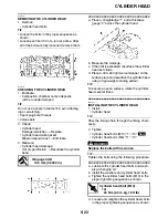
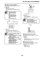
3. Install:
• Exhaust camshaft caps
• Intake camshaft caps
TIP
• Make sure each camshaft cap is installed in its
original place. Refer to the identification marks
as follows:
“E”, “E1”, “E2”, “E3”: Exhaust
“I”, “I1”, “I2”, “I3”: Intake
• Make sure the arrow mark “a” on each cam-
shaft points towards the right side of the en-
gine.
• Make sure the holes “b” in the camshafts are
aligned with arrow mark “a” on the camshaft
caps.
4. Install:
• Camshaft cap bolts
NOTICE
ECA13730
The camshaft cap bolts must be tightened
evenly or damage to the cylinder head, cam-
shaft caps, and camshafts will result.
TIP
Tighten the camshaft cap bolts in stages and in
a crisscross pattern, working from the inner caps
out.
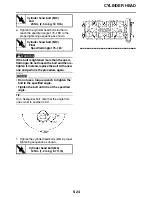
5. Align:
• “T” mark on the pickup rotor
(with the crankcase mating surface)
▼▼▼
▼
▼ ▼▼▼
▼
▼ ▼▼▼
▼
▼ ▼▼▼
▼
▼ ▼▼▼
▼
▼ ▼▼▼
▼
▼▼▼
a. Turn the crankshaft clockwise.
b. When piston #1 is at TDC on the compres-
sion stroke, align the “T” mark “a” on the pick-
up rotor with the crankcase mating surface
“b”.
▲▲▲
▲
▲ ▲▲▲
▲
▲ ▲▲▲
▲
▲ ▲▲▲
▲
▲ ▲▲▲
▲
▲ ▲▲▲
▲
▲▲▲
6. Install:
• Timing chain tensioner
• Timing chain tensioner gasket
▼▼▼
▼
▼ ▼▼▼
▼
▼ ▼▼▼
▼
▼ ▼▼▼
▼
▼ ▼▼▼
▼
▼ ▼▼▼
▼
▼▼▼
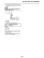
a. While lightly pressing the timing chain ten-
sioner rod by hand, turn the tensioner rod ful-
ly clockwise with a thin screwdriver “1”.
b. With the timing chain tensioner rod turned all
the way into the timing chain tensioner hous-
ing (with the thin screwdriver still installed), in-
stall the gasket and the timing chain tensioner
“2” onto the cylinder block.
c. Tighten the timing chain tensioner bolts “3” to
the specified torque.
T
R
.
.
Camshaft cap bolt
10 Nm (1.0 m·kg, 7.2 ft·lb)
E1
E2
E3 E
I1
I2
I3
I
T
R
.
.
Timing chain tensioner bolt
10 Nm (1.0 m·kg, 7.2 ft·lb)
b
a
New
Summary of Contents for FJR13AY 2009
Page 1: ...2009 SERVICE MANUAL FJR13AY C FJR13AEY C LIT 11616 22 73 3P6 28197 12 ...
Page 6: ......
Page 8: ......
Page 80: ...LUBRICATION SYSTEM CHART AND DIAGRAMS 2 31 EAS20410 LUBRICATION DIAGRAMS 5 6 7 1 2 3 4 ...
Page 82: ...LUBRICATION SYSTEM CHART AND DIAGRAMS 2 33 1 3 2 ...
Page 83: ...LUBRICATION SYSTEM CHART AND DIAGRAMS 2 34 1 Main axle 2 Drive axle 3 Oil delivery pipe 1 ...
Page 84: ...LUBRICATION SYSTEM CHART AND DIAGRAMS 2 35 6 5 4 3 2 1 ...
Page 86: ...LUBRICATION SYSTEM CHART AND DIAGRAMS 2 37 1 2 3 4 5 6 7 8 9 ...
Page 88: ...LUBRICATION SYSTEM CHART AND DIAGRAMS 2 39 4 5 3 2 1 9 8 6 7 ...
Page 92: ...COOLING SYSTEM DIAGRAMS 2 43 A A 7 1 2 3 4 5 5 7 8 6 8 9 10 11 12 ...
Page 98: ...CABLE ROUTING FJR13A 2 49 2 3 4 5 6 7 8 9 11 10 12 13 14 15 16 A B C D E F 1 1 ...
Page 100: ...CABLE ROUTING FJR13A 2 51 1 2 3 4 5 6 7 8 A B C D E 9 10 11 12 13 ...
Page 108: ...CABLE ROUTING FJR13A 2 59 1 2 3 4 A B B C D E ...
Page 110: ...CABLE ROUTING FJR13A 2 61 A 1 A A B P O C D E F G H I J K L M N 2 3 4 5 6 7 8 9 10 A 11 ...
Page 118: ...CABLE ROUTING FJR13AE 2 69 2 3 4 5 6 7 8 9 11 12 13 14 15 16 17 A B C E D F 1 1 H 10 18 G ...
Page 120: ...CABLE ROUTING FJR13AE 2 71 1 2 3 4 5 6 7 8 A B C D E 9 10 11 12 13 ...
Page 128: ...CABLE ROUTING FJR13AE 2 79 1 4 2 5 6 A B C D D E 3 F G ...
Page 130: ...CABLE ROUTING FJR13AE 2 81 A 1 A A B P O C D E F G H I J K L M N 2 3 4 5 6 7 8 9 10 A 11 ...
Page 134: ...CABLE ROUTING FJR13AE 2 85 ...
Page 137: ......
Page 196: ...GENERAL CHASSIS 4 11 b a 1 2 ...
Page 302: ...SHAFT DRIVE 4 117 ...
Page 326: ...CAMSHAFTS 5 21 ...
Page 424: ...CONNECTING RODS AND PISTONS 5 119 ...
Page 462: ...WATER PUMP 6 15 ...
Page 473: ...THROTTLE BODIES 7 10 ...
Page 474: ...AIR INDUCTION SYSTEM 7 11 EAS27040 AIR INDUCTION SYSTEM 1 2 3 4 5 1 1 1 1 2 2 5 2 3 3 4 7 8 6 ...
Page 483: ......
Page 495: ...IGNITION SYSTEM 8 12 ...
Page 511: ...ELECTRIC STARTING SYSTEM 8 28 ...
Page 513: ...CHARGING SYSTEM 8 30 2 Rectifier regulator 3 AC magneto 8 Main fuse 10 Battery ...
Page 515: ...CHARGING SYSTEM 8 32 ...
Page 539: ...COOLING SYSTEM 8 56 ...
Page 587: ...FUEL PUMP SYSTEM 8 104 ...
Page 599: ...ACCESSORY BOX SYSTEM 8 116 ...
Page 609: ...ABS ANTI LOCK BRAKE SYSTEM 8 126 ...
Page 698: ...ELECTRICAL COMPONENTS 8 215 FJR13A 5 1 3 2 17 8 10 11 12 13 14 15 16 7 6 4 9 ...
Page 700: ...ELECTRICAL COMPONENTS 8 217 FJR13AE 13 16 18 17 2 3 4 5 6 7 8 1 9 10 11 12 15 14 19 ...
Page 702: ...ELECTRICAL COMPONENTS 8 219 FJR13AE 1 19 3 2 5 7 9 8 12 13 14 15 16 11 10 18 17 6 4 ...
Page 730: ...ELECTRICAL COMPONENTS 8 247 ...
Page 739: ......
Page 740: ...YAMAHA MOTOR CO LTD 2500 SHINGAI IWATA SHIZUOKA JAPAN ...


