CLUTCH
5-64
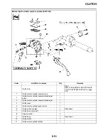
3. Install:
• Clutch boss assembly “1”
TIP
• If the wire circlip “2” has been removed, care-
fully install a new one.
• Install the clutch damper spring “3” with the
“OUTSIDE” mark facing out.
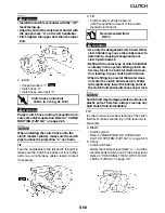
4. Install:
• Clutch boss “1”
• Lock washer “2”
• Clutch boss nut “3”
TIP
• Install the clutch boss nut with its large inner di-
ameter side facing inward as shown in the illus-
tration.
• While holding the clutch boss with the univer-
sal clutch holder “4”, tighten the clutch boss
nut.
5. Bend the lock washer tab along a flat side of
the nut.
6. Lubricate:
• Friction plates
• Clutch plates
(with the recommended lubricant)
7. Install:
• Friction plates
• Clutch plates
TIP
First, install a friction plate and then alternate be-
tween a clutch plate and a friction plate.
8. Install:
• Clutch spring bolts
TIP
Tighten the clutch spring bolts in stages and in a
crisscross pattern.
9. Install:
• Rear balancer weight
Refer to “BALANCERS” on page 5-136.
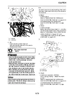
10.Install:
• Clutch cover
TIP
Tighten the clutch cover bolts in the proper tight-
ening sequence as shown.
EAS3P6N002
INSTALLING THE CLUTCH (FJR13AE)
1. Install:
• Clutch housing “1”
TIP
• Make sure that the projections “a” in the clutch
housing align with the slots “b” in the oil pump
drive sprocket.
T
R
.
.
Clutch boss nut
90 Nm (9.0 m·kg, 65 ft·lb)
Universal clutch holder
90890-04086
YM-91042
1
3
2
New
New
Recommended lubricant
Engine oil
T
R
.
.
Clutch spring bolt
8 Nm (0.8 m·kg, 5.8 ft·lb)
T
R
.
.
Clutch cover bolt
12 Nm (1.2 m·kg, 8.7 ft·lb)
8
9
10
1,11
2,12
3,13
5
7
6
4
Summary of Contents for FJR13AY 2009
Page 1: ...2009 SERVICE MANUAL FJR13AY C FJR13AEY C LIT 11616 22 73 3P6 28197 12 ...
Page 6: ......
Page 8: ......
Page 80: ...LUBRICATION SYSTEM CHART AND DIAGRAMS 2 31 EAS20410 LUBRICATION DIAGRAMS 5 6 7 1 2 3 4 ...
Page 82: ...LUBRICATION SYSTEM CHART AND DIAGRAMS 2 33 1 3 2 ...
Page 83: ...LUBRICATION SYSTEM CHART AND DIAGRAMS 2 34 1 Main axle 2 Drive axle 3 Oil delivery pipe 1 ...
Page 84: ...LUBRICATION SYSTEM CHART AND DIAGRAMS 2 35 6 5 4 3 2 1 ...
Page 86: ...LUBRICATION SYSTEM CHART AND DIAGRAMS 2 37 1 2 3 4 5 6 7 8 9 ...
Page 88: ...LUBRICATION SYSTEM CHART AND DIAGRAMS 2 39 4 5 3 2 1 9 8 6 7 ...
Page 92: ...COOLING SYSTEM DIAGRAMS 2 43 A A 7 1 2 3 4 5 5 7 8 6 8 9 10 11 12 ...
Page 98: ...CABLE ROUTING FJR13A 2 49 2 3 4 5 6 7 8 9 11 10 12 13 14 15 16 A B C D E F 1 1 ...
Page 100: ...CABLE ROUTING FJR13A 2 51 1 2 3 4 5 6 7 8 A B C D E 9 10 11 12 13 ...
Page 108: ...CABLE ROUTING FJR13A 2 59 1 2 3 4 A B B C D E ...
Page 110: ...CABLE ROUTING FJR13A 2 61 A 1 A A B P O C D E F G H I J K L M N 2 3 4 5 6 7 8 9 10 A 11 ...
Page 118: ...CABLE ROUTING FJR13AE 2 69 2 3 4 5 6 7 8 9 11 12 13 14 15 16 17 A B C E D F 1 1 H 10 18 G ...
Page 120: ...CABLE ROUTING FJR13AE 2 71 1 2 3 4 5 6 7 8 A B C D E 9 10 11 12 13 ...
Page 128: ...CABLE ROUTING FJR13AE 2 79 1 4 2 5 6 A B C D D E 3 F G ...
Page 130: ...CABLE ROUTING FJR13AE 2 81 A 1 A A B P O C D E F G H I J K L M N 2 3 4 5 6 7 8 9 10 A 11 ...
Page 134: ...CABLE ROUTING FJR13AE 2 85 ...
Page 137: ......
Page 196: ...GENERAL CHASSIS 4 11 b a 1 2 ...
Page 302: ...SHAFT DRIVE 4 117 ...
Page 326: ...CAMSHAFTS 5 21 ...
Page 424: ...CONNECTING RODS AND PISTONS 5 119 ...
Page 462: ...WATER PUMP 6 15 ...
Page 473: ...THROTTLE BODIES 7 10 ...
Page 474: ...AIR INDUCTION SYSTEM 7 11 EAS27040 AIR INDUCTION SYSTEM 1 2 3 4 5 1 1 1 1 2 2 5 2 3 3 4 7 8 6 ...
Page 483: ......
Page 495: ...IGNITION SYSTEM 8 12 ...
Page 511: ...ELECTRIC STARTING SYSTEM 8 28 ...
Page 513: ...CHARGING SYSTEM 8 30 2 Rectifier regulator 3 AC magneto 8 Main fuse 10 Battery ...
Page 515: ...CHARGING SYSTEM 8 32 ...
Page 539: ...COOLING SYSTEM 8 56 ...
Page 587: ...FUEL PUMP SYSTEM 8 104 ...
Page 599: ...ACCESSORY BOX SYSTEM 8 116 ...
Page 609: ...ABS ANTI LOCK BRAKE SYSTEM 8 126 ...
Page 698: ...ELECTRICAL COMPONENTS 8 215 FJR13A 5 1 3 2 17 8 10 11 12 13 14 15 16 7 6 4 9 ...
Page 700: ...ELECTRICAL COMPONENTS 8 217 FJR13AE 13 16 18 17 2 3 4 5 6 7 8 1 9 10 11 12 15 14 19 ...
Page 702: ...ELECTRICAL COMPONENTS 8 219 FJR13AE 1 19 3 2 5 7 9 8 12 13 14 15 16 11 10 18 17 6 4 ...
Page 730: ...ELECTRICAL COMPONENTS 8 247 ...
Page 739: ......
Page 740: ...YAMAHA MOTOR CO LTD 2500 SHINGAI IWATA SHIZUOKA JAPAN ...


