3-54
CHECKING THE TIRES
CHK
ADJ
WARNING
WARNING
S
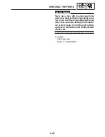
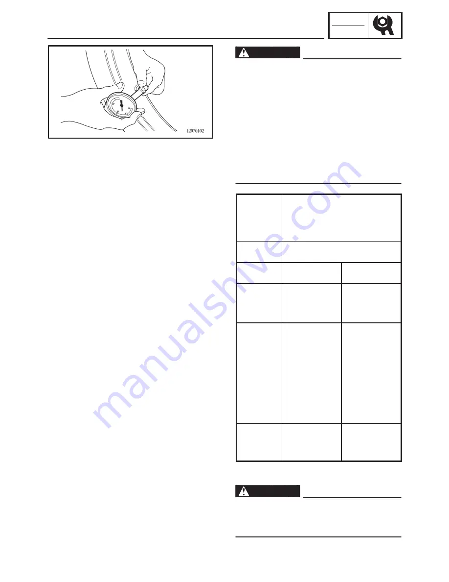
The tire pressure should only be checked
and regulated when the tire temperature
equals the ambient air temperature.
S
The tire pressure and the suspension must
be adjusted according to the total weight
(including cargo, rider, passenger and ac-
cessories) and the anticipated riding
speed.
S
Operation of an overloaded motorcycle
could cause tire damage, an accident or an
injury.
NEVER OVERLOAD THE MOTORCYCLE.
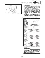
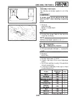
Basic
weight
(with oil
and a full
fuel tank)
207 kg (456 lb)
208 kg (459 lb) for CAL
Maximum
load*
190 kg (419 lb)
189 kg (417 lb) for CAL
Cold tire
pressure
Front
Rear
Up to
90 kg
(198 lb)
load*
225 kPa
(2.25 kgf/cm
2
,
2.25 bar,
33psi)
250 kPa
(2.5 kgf / cm
2
,
2.5 bar,
35.6 psi)
90 kg
X
190 kg
(198
X
419 lb)
90 kg
X
189 kg
(198
X
417 lb)
for CAL
maximum
load*
250 kPa
(2.5 kgf / cm
2
,
2.5 bar,
35.6 psi)
290 kPa
(2.9 kgf / cm
2
,
2.9 bar,
41.3 psi)
High-
speed
riding
225 kPa
(2.25 kgf/cm
2
,
2.25 bar,
33 psi)
250 kPa
(2.5 kgf / cm
2
,
2.5 bar,
35.6 psi)
* Total weight of rider, passenger, cargo and ac-
cessories
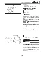
It is dangerous to ride with a worn-out tire.
When the tire tread reaches the wear limit,
replace the tire immediately.
Summary of Contents for FZ6-SS
Page 1: ......
Page 47: ...2 20 TIGHTENING TORQUES SPEC Cylinder head tightening sequence Crankcase tightening sequence...
Page 52: ...2 25 COOLING SYSTEM DIAGRAMS SPEC 1 Radiator 2 Oil cooler COOLING SYSTEM DIAGRAMS...
Page 53: ...2 26 COOLING SYSTEM DIAGRAMS SPEC 1 Water pump 2 Oil cooler 3 Radiator...
Page 54: ...2 27 COOLING SYSTEM DIAGRAMS SPEC 1 Oil cooler 2 Water pump...
Page 55: ...2 28 COOLING SYSTEM DIAGRAMS SPEC 1 Radiator 2 Thermostat...
Page 56: ...2 29 ENGINE OIL LUBRICATION CHART SPEC ENGINE OIL LUBRICATION CHART...
Page 58: ...2 31 LUBRICATION DIAGRAMS SPEC 1 Oil pump 2 Exhaust camshaft 3 Intake camshaft 4 Oil strainer...
Page 59: ...2 32 LUBRICATION DIAGRAMS SPEC 1 Oil cooler 2 Oil strainer 3 Oil level switch 4 Oil pump...
Page 60: ...2 33 LUBRICATION DIAGRAMS SPEC 1 Main axle 2 Oil pump 3 Relief valve...
Page 62: ...2 35 LUBRICATION DIAGRAMS SPEC 1 Main axle 2 Drive axle...
Page 398: ...8 27 LIGHTING SYSTEM ELEC EAS00780 LIGHTING SYSTEM CIRCUIT DIAGRAM...
Page 405: ...8 34 SIGNALING SYSTEM ELEC EAS00793 SIGNALING SYSTEM CIRCUIT DIAGRAM...
Page 433: ...FZ6 SS FZ6 SSC WIRING DIAGRAM...
Page 435: ......

