3-56
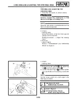
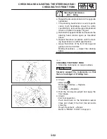
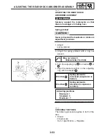
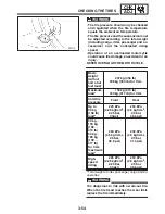
CHECKING THE TIRES/CHECKING THE WHEELS
CHK
ADJ
WARNING
NOTE:
WARNING
NOTE:
Front tire
Manufacturer
Size
Model
BRIDGESTONE
120 / 70ZR 17
M / C (58W)
BT020F
GG
DUNLOP
120 / 70ZR 17
M / C (58W)
D252F
Rear tire
Manufacturer
Size
Model
BRIDGESTONE
180 / 55ZR 17
M / C (73W)
BT020R
GG
DUNLOP
180 / 55ZR 17
M / C (73W)
D252
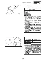
New tires and wheels have a relatively low
grip on the road surface until they have been
slightly worn. Therefore, approximately 100
km should be traveled at normal speed be-
fore any high-speed riding is done.
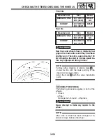
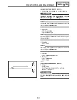
For tires with a direction of rotation mark
1
:
S
Install the tire with the mark pointing in the
direction of wheel rotation.
S
Align the mark
2
with the valve installation
point.
EAS00168
CHECKING THE WHEELS
The following procedure applies to both of the
wheels.
1. Check:
S
wheel
Damage / out-of-round
!
Replace.
Never attempt to make any repairs to the
wheel.
After a tire or wheel has been changed or re-
placed, always balance the wheel.
Summary of Contents for FZ6-SS
Page 1: ......
Page 47: ...2 20 TIGHTENING TORQUES SPEC Cylinder head tightening sequence Crankcase tightening sequence...
Page 52: ...2 25 COOLING SYSTEM DIAGRAMS SPEC 1 Radiator 2 Oil cooler COOLING SYSTEM DIAGRAMS...
Page 53: ...2 26 COOLING SYSTEM DIAGRAMS SPEC 1 Water pump 2 Oil cooler 3 Radiator...
Page 54: ...2 27 COOLING SYSTEM DIAGRAMS SPEC 1 Oil cooler 2 Water pump...
Page 55: ...2 28 COOLING SYSTEM DIAGRAMS SPEC 1 Radiator 2 Thermostat...
Page 56: ...2 29 ENGINE OIL LUBRICATION CHART SPEC ENGINE OIL LUBRICATION CHART...
Page 58: ...2 31 LUBRICATION DIAGRAMS SPEC 1 Oil pump 2 Exhaust camshaft 3 Intake camshaft 4 Oil strainer...
Page 59: ...2 32 LUBRICATION DIAGRAMS SPEC 1 Oil cooler 2 Oil strainer 3 Oil level switch 4 Oil pump...
Page 60: ...2 33 LUBRICATION DIAGRAMS SPEC 1 Main axle 2 Oil pump 3 Relief valve...
Page 62: ...2 35 LUBRICATION DIAGRAMS SPEC 1 Main axle 2 Drive axle...
Page 398: ...8 27 LIGHTING SYSTEM ELEC EAS00780 LIGHTING SYSTEM CIRCUIT DIAGRAM...
Page 405: ...8 34 SIGNALING SYSTEM ELEC EAS00793 SIGNALING SYSTEM CIRCUIT DIAGRAM...
Page 433: ...FZ6 SS FZ6 SSC WIRING DIAGRAM...
Page 435: ......

