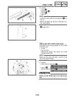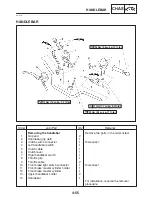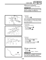
4-49
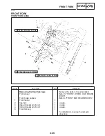
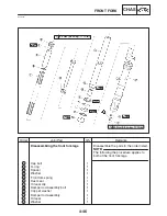
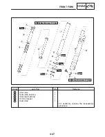
FRONT FORK
CHAS
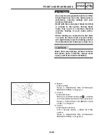
CAUTION:
NOTE:
CAUTION:
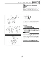
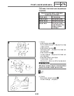
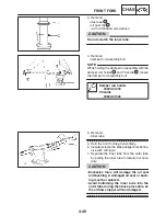
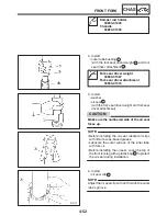
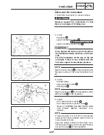
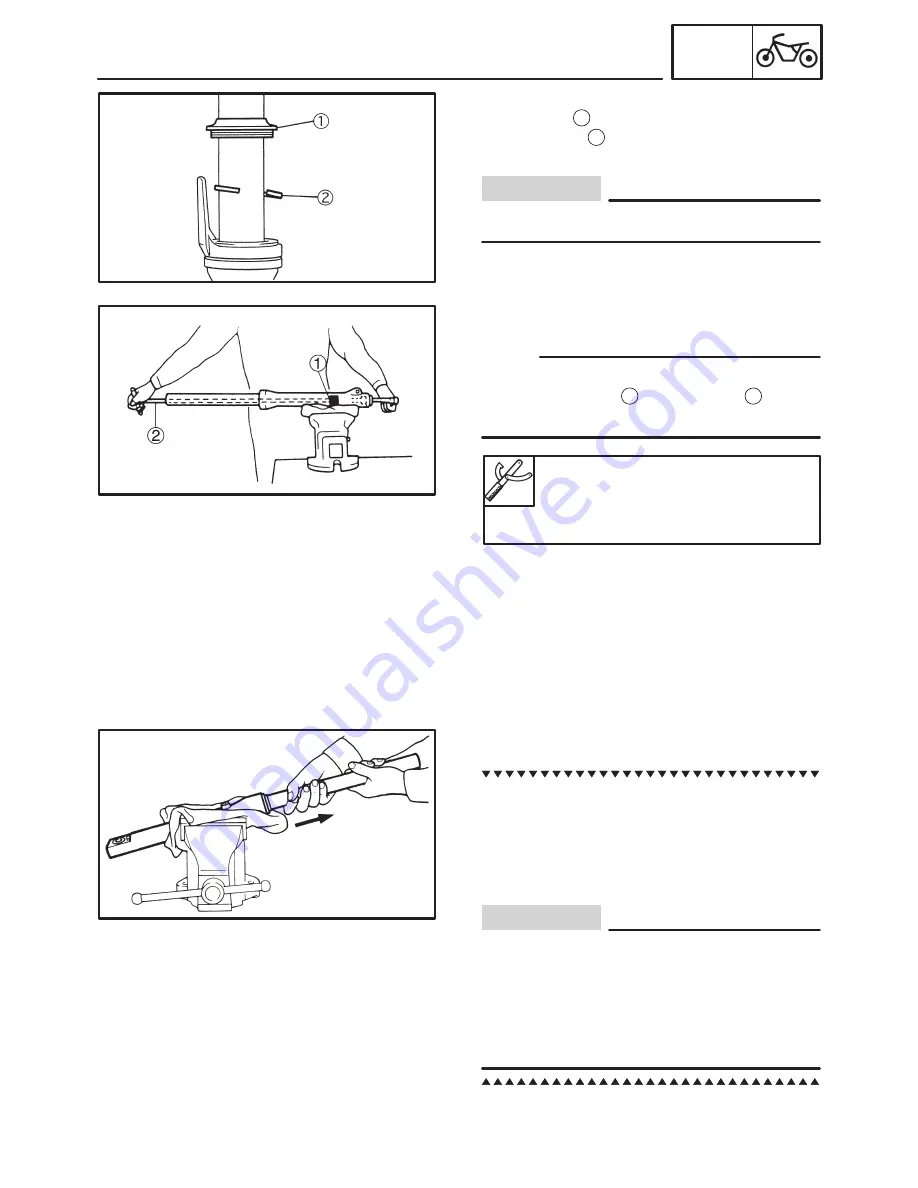
3. Remove:
S
dust seal
1
S
oil seal clip
2
(with a flat-head screwdriver)
Do not scratch the inner tube.
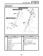
4. Remove:
S
damper rod assembly bolt
While holding the damper rod assembly with the
damper rod holder
1
and T-handle
2
, loosen
the damper rod assembly bolt.
Damper rod holder
90890-01294
T-handle
90890-01326
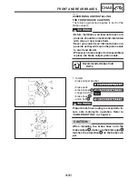
5. Remove:
S
inner tube
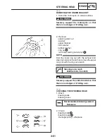
a. Hold the front fork leg horizontally.
b. Securely clamp the brake caliper bracket in a
vise with soft jaws.
c. Separate the inner tube from the outer tube
by pulling the inner tube forcefully but care-
fully.
S
Excessive force will damage the oil seal
and bushing. A damaged oil seal or bush-
ing must be replaced.
S
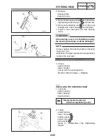
Avoid bottoming the inner tube into the
outer tube during the above procedure, as
the oil flow stopper will be damaged.
Summary of Contents for FZ6-SS
Page 1: ......
Page 47: ...2 20 TIGHTENING TORQUES SPEC Cylinder head tightening sequence Crankcase tightening sequence...
Page 52: ...2 25 COOLING SYSTEM DIAGRAMS SPEC 1 Radiator 2 Oil cooler COOLING SYSTEM DIAGRAMS...
Page 53: ...2 26 COOLING SYSTEM DIAGRAMS SPEC 1 Water pump 2 Oil cooler 3 Radiator...
Page 54: ...2 27 COOLING SYSTEM DIAGRAMS SPEC 1 Oil cooler 2 Water pump...
Page 55: ...2 28 COOLING SYSTEM DIAGRAMS SPEC 1 Radiator 2 Thermostat...
Page 56: ...2 29 ENGINE OIL LUBRICATION CHART SPEC ENGINE OIL LUBRICATION CHART...
Page 58: ...2 31 LUBRICATION DIAGRAMS SPEC 1 Oil pump 2 Exhaust camshaft 3 Intake camshaft 4 Oil strainer...
Page 59: ...2 32 LUBRICATION DIAGRAMS SPEC 1 Oil cooler 2 Oil strainer 3 Oil level switch 4 Oil pump...
Page 60: ...2 33 LUBRICATION DIAGRAMS SPEC 1 Main axle 2 Oil pump 3 Relief valve...
Page 62: ...2 35 LUBRICATION DIAGRAMS SPEC 1 Main axle 2 Drive axle...
Page 398: ...8 27 LIGHTING SYSTEM ELEC EAS00780 LIGHTING SYSTEM CIRCUIT DIAGRAM...
Page 405: ...8 34 SIGNALING SYSTEM ELEC EAS00793 SIGNALING SYSTEM CIRCUIT DIAGRAM...
Page 433: ...FZ6 SS FZ6 SSC WIRING DIAGRAM...
Page 435: ......

