5-24
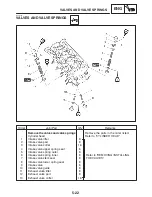
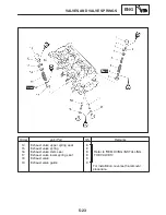
VALVES AND VALVE SPRINGS
ENG
NOTE:
NOTE:
NOTE:
NOTE:
EAS00238
REMOVING THE VALVES
The following procedure applies to all of the
valves and related components.
Before removing the internal parts of the cylin-
der head (e.g., valves, valve springs, valve
seats), make sure the valves properly seal.
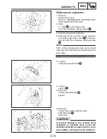
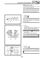
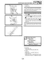
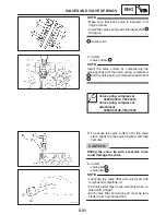
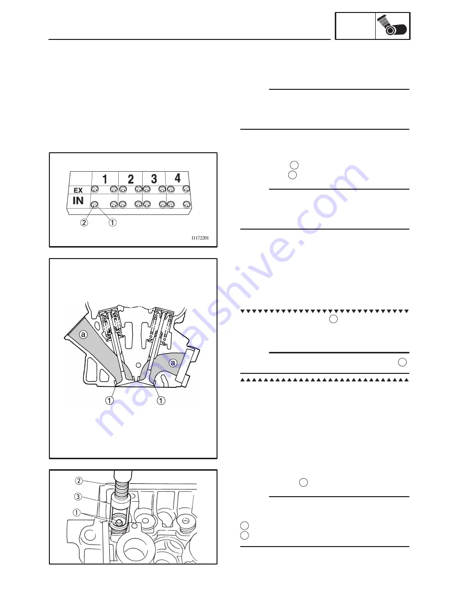
1. Remove:
S
valve lifter
1
S
valve pad
2
Make a note of the position of each valve lifter
and valve pad so that they can be reinstalled in
their original place.
2. Check:
S
valve sealing
Leakage at the valve seat
!
Check the valve
face, valve seat, and valve seat width.
Refer to “CHECKING THE VALVE SEATS”.
a. Pour a clean solvent
a
into the intake and
exhaust ports.
b. Check that the valves properly seal.
There should be no leakage at the valve seat
1
.
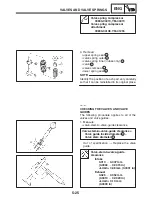
3. Remove:
S
valve cotters
1
Remove the valve cotters by compressing the
valve springs with the valve spring compressor
2
and the valve spring compressor attachment
3
.
Summary of Contents for FZ6-SS
Page 1: ......
Page 47: ...2 20 TIGHTENING TORQUES SPEC Cylinder head tightening sequence Crankcase tightening sequence...
Page 52: ...2 25 COOLING SYSTEM DIAGRAMS SPEC 1 Radiator 2 Oil cooler COOLING SYSTEM DIAGRAMS...
Page 53: ...2 26 COOLING SYSTEM DIAGRAMS SPEC 1 Water pump 2 Oil cooler 3 Radiator...
Page 54: ...2 27 COOLING SYSTEM DIAGRAMS SPEC 1 Oil cooler 2 Water pump...
Page 55: ...2 28 COOLING SYSTEM DIAGRAMS SPEC 1 Radiator 2 Thermostat...
Page 56: ...2 29 ENGINE OIL LUBRICATION CHART SPEC ENGINE OIL LUBRICATION CHART...
Page 58: ...2 31 LUBRICATION DIAGRAMS SPEC 1 Oil pump 2 Exhaust camshaft 3 Intake camshaft 4 Oil strainer...
Page 59: ...2 32 LUBRICATION DIAGRAMS SPEC 1 Oil cooler 2 Oil strainer 3 Oil level switch 4 Oil pump...
Page 60: ...2 33 LUBRICATION DIAGRAMS SPEC 1 Main axle 2 Oil pump 3 Relief valve...
Page 62: ...2 35 LUBRICATION DIAGRAMS SPEC 1 Main axle 2 Drive axle...
Page 398: ...8 27 LIGHTING SYSTEM ELEC EAS00780 LIGHTING SYSTEM CIRCUIT DIAGRAM...
Page 405: ...8 34 SIGNALING SYSTEM ELEC EAS00793 SIGNALING SYSTEM CIRCUIT DIAGRAM...
Page 433: ...FZ6 SS FZ6 SSC WIRING DIAGRAM...
Page 435: ......

