5-52
CLUTCH
ENG
90 Nm (9.0 m
S
kg, 65 ft
S
lb)
NOTE:
EAS00287
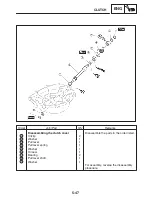
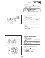
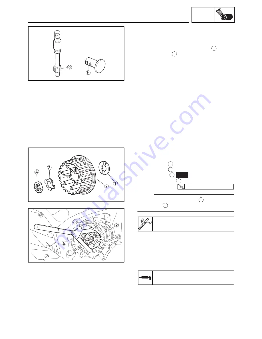
CHECKING THE PULL LEVER SHAFT AND
PULL ROD
1. Check:
S
pull lever shaft pinion gear teeth
a
S
pull rod teeth
b
Damage / wear
!
Replace the pull rod and
pull lever shaft pinion gear as a set.
2. Check:
S
pull rod bearing
Damage / wear
!
Replace.
EAS00299
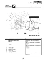
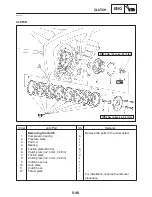
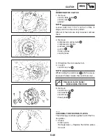
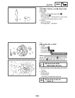
INSTALLING THE CLUTCH
1. Install:
S
thrust plate
1
S
clutch boss
2
S
lock washer
3
New
S
clutch boss nut
4
While holding the clutch boss
2
with the clutch
holding tool
5
, tighten the clutch boss nut.
Universal clutch holder
90890-04089, YM-91042
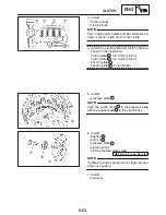
2. Bend the lock washer tab along a flat side of
the nut.
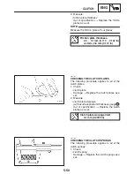
3. Lubricate:
S
friction plates
S
clutch plates
(with the recommended lubricant)
Recommended lubricant
Engine oil
Summary of Contents for FZ6-SS
Page 1: ......
Page 47: ...2 20 TIGHTENING TORQUES SPEC Cylinder head tightening sequence Crankcase tightening sequence...
Page 52: ...2 25 COOLING SYSTEM DIAGRAMS SPEC 1 Radiator 2 Oil cooler COOLING SYSTEM DIAGRAMS...
Page 53: ...2 26 COOLING SYSTEM DIAGRAMS SPEC 1 Water pump 2 Oil cooler 3 Radiator...
Page 54: ...2 27 COOLING SYSTEM DIAGRAMS SPEC 1 Oil cooler 2 Water pump...
Page 55: ...2 28 COOLING SYSTEM DIAGRAMS SPEC 1 Radiator 2 Thermostat...
Page 56: ...2 29 ENGINE OIL LUBRICATION CHART SPEC ENGINE OIL LUBRICATION CHART...
Page 58: ...2 31 LUBRICATION DIAGRAMS SPEC 1 Oil pump 2 Exhaust camshaft 3 Intake camshaft 4 Oil strainer...
Page 59: ...2 32 LUBRICATION DIAGRAMS SPEC 1 Oil cooler 2 Oil strainer 3 Oil level switch 4 Oil pump...
Page 60: ...2 33 LUBRICATION DIAGRAMS SPEC 1 Main axle 2 Oil pump 3 Relief valve...
Page 62: ...2 35 LUBRICATION DIAGRAMS SPEC 1 Main axle 2 Drive axle...
Page 398: ...8 27 LIGHTING SYSTEM ELEC EAS00780 LIGHTING SYSTEM CIRCUIT DIAGRAM...
Page 405: ...8 34 SIGNALING SYSTEM ELEC EAS00793 SIGNALING SYSTEM CIRCUIT DIAGRAM...
Page 433: ...FZ6 SS FZ6 SSC WIRING DIAGRAM...
Page 435: ......

