5-61
OIL PAN AND OIL PUMP
ENG
NOTE:
12 Nm (1.2 m
S
kg, 8.7 ft
S
lb)
10 Nm (1.0 m
S
kg, 7.2 ft
S
lb)
43 Nm (4.3 m
S
kg, 31 ft
S
lb)
WARNING
NOTE:
EAS00378
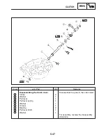
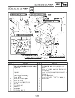
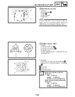
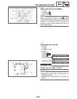
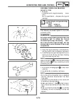
INSTALLING THE OIL STRAINER
1. Install:
S
oil strainer
1
S
relief valve
2
Make sure to check the arrow mark
a
located
on the oil strainer housing for the front and rear
direction of the engine and then install the oil
strainer so that its arrow mark points to the front
side of the engine.
EAS00380
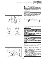
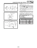
INSTALLING THE OIL PAN
1. Install:
S
oil pipe
S
oil delivery pipe
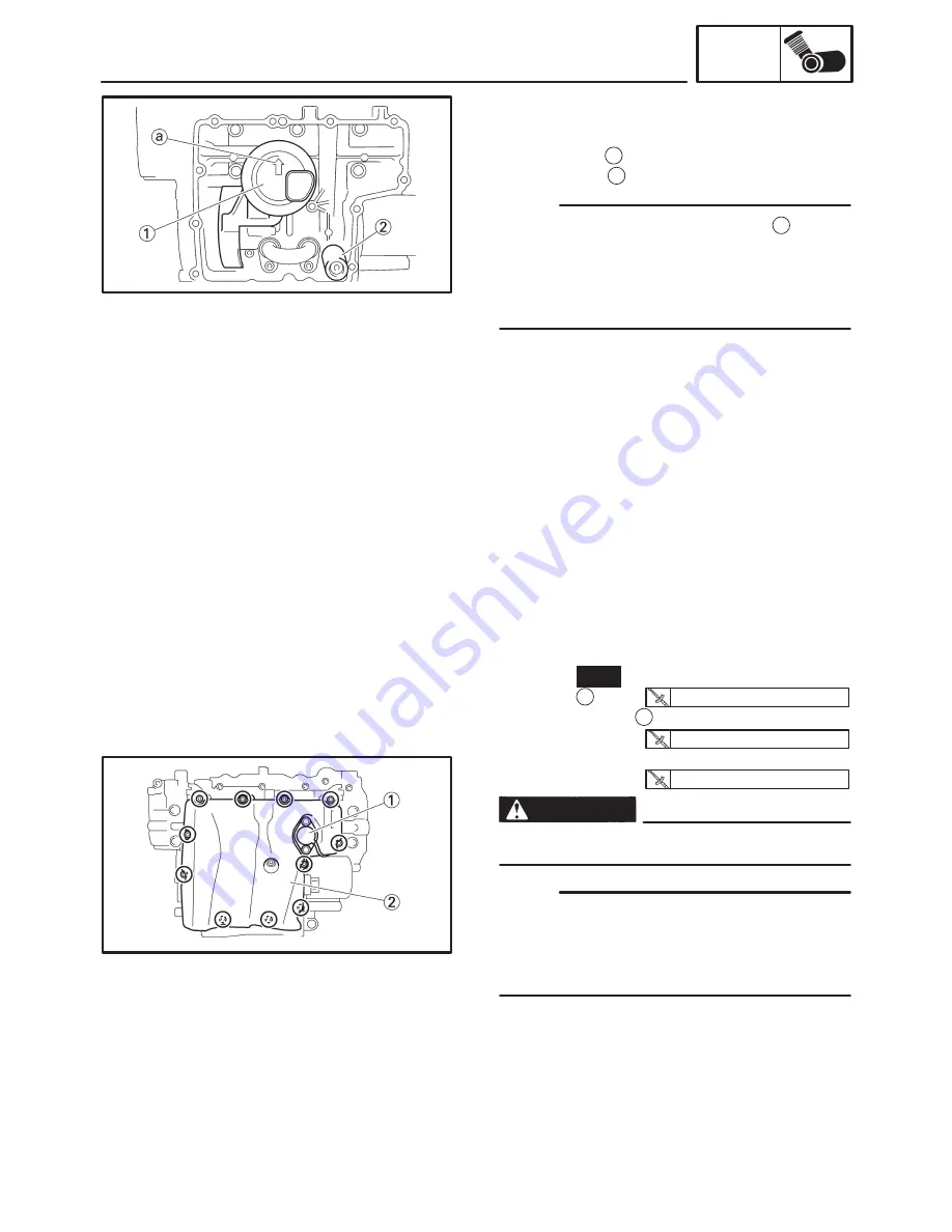
2. Install:
S
dowel pins
S
gasket
New
S
oil pan
1
S
oil level switch
2
S
engine oil drain bolt
Always use new copper washers.
S
Tighten the oil pan bolts in stages and in a
crisscross pattern.
S
Lubricate the oil level switch O-ring with en-
gine oil.
Summary of Contents for FZ6-SS
Page 1: ......
Page 47: ...2 20 TIGHTENING TORQUES SPEC Cylinder head tightening sequence Crankcase tightening sequence...
Page 52: ...2 25 COOLING SYSTEM DIAGRAMS SPEC 1 Radiator 2 Oil cooler COOLING SYSTEM DIAGRAMS...
Page 53: ...2 26 COOLING SYSTEM DIAGRAMS SPEC 1 Water pump 2 Oil cooler 3 Radiator...
Page 54: ...2 27 COOLING SYSTEM DIAGRAMS SPEC 1 Oil cooler 2 Water pump...
Page 55: ...2 28 COOLING SYSTEM DIAGRAMS SPEC 1 Radiator 2 Thermostat...
Page 56: ...2 29 ENGINE OIL LUBRICATION CHART SPEC ENGINE OIL LUBRICATION CHART...
Page 58: ...2 31 LUBRICATION DIAGRAMS SPEC 1 Oil pump 2 Exhaust camshaft 3 Intake camshaft 4 Oil strainer...
Page 59: ...2 32 LUBRICATION DIAGRAMS SPEC 1 Oil cooler 2 Oil strainer 3 Oil level switch 4 Oil pump...
Page 60: ...2 33 LUBRICATION DIAGRAMS SPEC 1 Main axle 2 Oil pump 3 Relief valve...
Page 62: ...2 35 LUBRICATION DIAGRAMS SPEC 1 Main axle 2 Drive axle...
Page 398: ...8 27 LIGHTING SYSTEM ELEC EAS00780 LIGHTING SYSTEM CIRCUIT DIAGRAM...
Page 405: ...8 34 SIGNALING SYSTEM ELEC EAS00793 SIGNALING SYSTEM CIRCUIT DIAGRAM...
Page 433: ...FZ6 SS FZ6 SSC WIRING DIAGRAM...
Page 435: ......

