6-16
WATER PUMP
COOL
10 Nm (1.0 m
S
kg, 7.2 ft
S
lb)
NOTE:
NOTE:
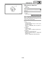
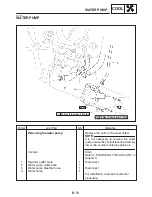
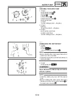
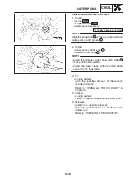
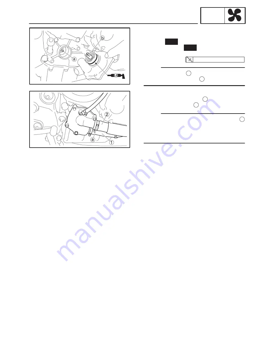
INSTALLING THE WATER PUMP
1. Install:
S
O-ring
New
S
copper washer
New
S
water pump assembly
Align the projection
a
at the oil pump shaft and
water pump shaft groove
b
.
2. Install:
S
water pump outlet hose
1
S
radiator outlet hose
2
S
Install the radiator outlet hose with white
a
mark positioned outside.
S
Install the hose clamp with its screw head
pointed to the inner side.
3. Fill:
S
cooling system
(with the specified amount of the recom-
mended coolant)
Refer to “CHANGING THE COOLANT” in
chapter 3.
4. Check:
S
cooling system
Leaks
!
Repair or replace any faulty part.
5. Measure:
S
radiator cap opening pressure
Below the specified pressure !I! Replace the
radiator cap.
Refer to “CHECKING THE RADIATOR”.
Summary of Contents for FZ6-SS
Page 1: ......
Page 47: ...2 20 TIGHTENING TORQUES SPEC Cylinder head tightening sequence Crankcase tightening sequence...
Page 52: ...2 25 COOLING SYSTEM DIAGRAMS SPEC 1 Radiator 2 Oil cooler COOLING SYSTEM DIAGRAMS...
Page 53: ...2 26 COOLING SYSTEM DIAGRAMS SPEC 1 Water pump 2 Oil cooler 3 Radiator...
Page 54: ...2 27 COOLING SYSTEM DIAGRAMS SPEC 1 Oil cooler 2 Water pump...
Page 55: ...2 28 COOLING SYSTEM DIAGRAMS SPEC 1 Radiator 2 Thermostat...
Page 56: ...2 29 ENGINE OIL LUBRICATION CHART SPEC ENGINE OIL LUBRICATION CHART...
Page 58: ...2 31 LUBRICATION DIAGRAMS SPEC 1 Oil pump 2 Exhaust camshaft 3 Intake camshaft 4 Oil strainer...
Page 59: ...2 32 LUBRICATION DIAGRAMS SPEC 1 Oil cooler 2 Oil strainer 3 Oil level switch 4 Oil pump...
Page 60: ...2 33 LUBRICATION DIAGRAMS SPEC 1 Main axle 2 Oil pump 3 Relief valve...
Page 62: ...2 35 LUBRICATION DIAGRAMS SPEC 1 Main axle 2 Drive axle...
Page 398: ...8 27 LIGHTING SYSTEM ELEC EAS00780 LIGHTING SYSTEM CIRCUIT DIAGRAM...
Page 405: ...8 34 SIGNALING SYSTEM ELEC EAS00793 SIGNALING SYSTEM CIRCUIT DIAGRAM...
Page 433: ...FZ6 SS FZ6 SSC WIRING DIAGRAM...
Page 435: ......


