7-2
7
FUEL INJECTION SYSTEM
FI
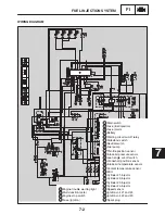
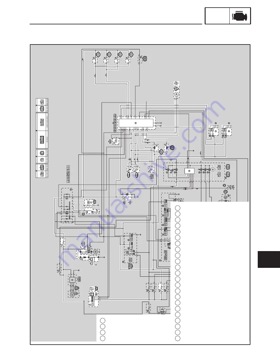
WIRING DIAGRAM
1
Main switch
5
Fuse (fuel injection)
6
Fuse (main)
9
Battery
10
Starting circuit cut-off relay
11
Sidestand switch
12
Neutral switch
13
Fuel pump
14
Throttle position sensor
15
Intake air pressure sensor
16
Lean angle cut-off switch
17
Crankshaft position sensor
18
Intake air temperature sensor
19
Coolant temperature sensor
20
ECU
21
Cylinder #1-injector
22
Cylinder #2-injector
23
Cylinder #3-injector
24
Cylinder #4-injector
26
Speed sensor
27
Ignition coil #1 and #4
28
Ignition coil #2 and #3
29
Spark plug
32
Engine trouble warning light
34
Multi-function meter
40
Engine stop switch
47
Fuse (ignition)
Summary of Contents for FZ6-SS
Page 1: ......
Page 47: ...2 20 TIGHTENING TORQUES SPEC Cylinder head tightening sequence Crankcase tightening sequence...
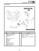
Page 52: ...2 25 COOLING SYSTEM DIAGRAMS SPEC 1 Radiator 2 Oil cooler COOLING SYSTEM DIAGRAMS...
Page 53: ...2 26 COOLING SYSTEM DIAGRAMS SPEC 1 Water pump 2 Oil cooler 3 Radiator...
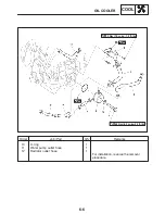
Page 54: ...2 27 COOLING SYSTEM DIAGRAMS SPEC 1 Oil cooler 2 Water pump...
Page 55: ...2 28 COOLING SYSTEM DIAGRAMS SPEC 1 Radiator 2 Thermostat...
Page 56: ...2 29 ENGINE OIL LUBRICATION CHART SPEC ENGINE OIL LUBRICATION CHART...
Page 58: ...2 31 LUBRICATION DIAGRAMS SPEC 1 Oil pump 2 Exhaust camshaft 3 Intake camshaft 4 Oil strainer...
Page 59: ...2 32 LUBRICATION DIAGRAMS SPEC 1 Oil cooler 2 Oil strainer 3 Oil level switch 4 Oil pump...
Page 60: ...2 33 LUBRICATION DIAGRAMS SPEC 1 Main axle 2 Oil pump 3 Relief valve...
Page 62: ...2 35 LUBRICATION DIAGRAMS SPEC 1 Main axle 2 Drive axle...
Page 398: ...8 27 LIGHTING SYSTEM ELEC EAS00780 LIGHTING SYSTEM CIRCUIT DIAGRAM...
Page 405: ...8 34 SIGNALING SYSTEM ELEC EAS00793 SIGNALING SYSTEM CIRCUIT DIAGRAM...
Page 433: ...FZ6 SS FZ6 SSC WIRING DIAGRAM...
Page 435: ......

