2-21
TIGHTENING TORQUES
SPEC
See
NOTE 3
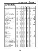
CHASSIS TIGHTENING TORQUES
Item
Thread
Tightening
Remarks
Item
size
Nm
m
S
kg
ft
S
lb
Remarks
Upper bracket pinch bolt
M8
30
3.0
22
Steering stem nut
M22
110
11
80
Upper bracket and upper handlebar holder
M8
23
2.3
17
Under bracket pinch bolt
–
30
3.0
22
Lower ring nut
M25
18
1.8
13
See NOTE 1
Front fork cap bolt
M35
24
2.4
17
Damper rod assembly bolt
M10
23
2.3
17
Pinch bolt (front wheel axle)
M8
23
2.3
17
Front brake master cylinder and master cylinder
bracket
M6
10
1.0
7.2
Front brake master cylinder cap screw
M4
2
0.2
1.4
Front brake hose union bolt
M10
30
3.0
22
Front brake hose holder and front fork
M6
10
1.0
7.2
Front cowling stay and frame
M8
33
3.3
24
Front cowling bracket and frame
M6
7
0.7
5.1
Front fender and front fork
M6
6
0.6
4.3
Clutch lever holder pinch bolt
M6
11
1.1
8.0
Engine mount bolts (left of front side)
M10
55
5.5
40
Engine mount bolts (left of rear side)
M10
55
5.5
40
Engine mount bolts (right of front side)
M10
55
5.5
40
See NOTE 2
Engine mount self locking nut (upper)
M10
55
5.5
40
Engine mount self locking nut (lower)
M10
55
5.5
40
Fornt frame and rear frame (upper)
M10
41
4.1
30
Front frame and rear frame (lower)
M10
41
4.1
30
Pivot shaft and frame
M18
120
12
87
Rear shock absorber and frame
M10
40
4.0
29
Rear shock absorber and rear arm
M10
40
4.0
29
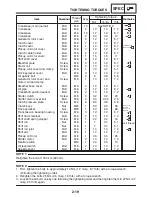
Seal guard and rear arm
M6
7
0.7
5.1
Rear fender and rear arm
M6
7
0.7
5.1
Rear brake hose holder and rear arm
M6
7
0.7
5.1
Fuel tank bracket and frame
M6
7
0.7
5.1
Fuel tank bracket and fuel tank
M6
7
0.7
5.1
Fuel tank and rear frame
M6
7
0.7
5.1
Fuel tank and fuel tank cap
M5
6
0.6
4.3
Fuel pump and fuel tank
M5
4
0.4
2.9
Ignition coil and battery box
M6
7
0.7
5.1
Seat lock and frame
M6
7
0.7
5.1
Rotor and mud guard
M6
3
0.3
2.2
Licence plate light and flap
M5
4
0.4
2.9
Front side reflector and front brake hose holder
M5
4
0.4
2.9
Rear side reflector and stay
M5
3
0.3
2.2
Rear reflector and flap
M5
4
0.4
2.9
Flap and bracket 6
M6
7
0.7
5.1
Blacket 6 and rear frame
M6
19
1.9
14
Seat handle and tail / brake right unit
M6
3
0.3
2.2
Rear fender cover and seat handle
M5
4
0.4
2.9
Seat handle bolt
M8
23
2.3
17
Muffler and rear fender
M6
7
0.7
5.1
Summary of Contents for FZ6-SS
Page 1: ......
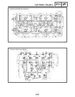
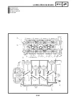
Page 47: ...2 20 TIGHTENING TORQUES SPEC Cylinder head tightening sequence Crankcase tightening sequence...
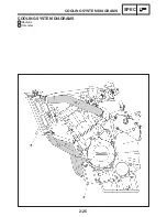
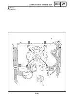
Page 52: ...2 25 COOLING SYSTEM DIAGRAMS SPEC 1 Radiator 2 Oil cooler COOLING SYSTEM DIAGRAMS...
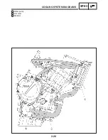
Page 53: ...2 26 COOLING SYSTEM DIAGRAMS SPEC 1 Water pump 2 Oil cooler 3 Radiator...
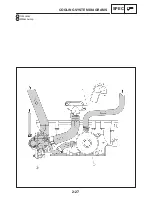
Page 54: ...2 27 COOLING SYSTEM DIAGRAMS SPEC 1 Oil cooler 2 Water pump...
Page 55: ...2 28 COOLING SYSTEM DIAGRAMS SPEC 1 Radiator 2 Thermostat...
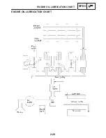
Page 56: ...2 29 ENGINE OIL LUBRICATION CHART SPEC ENGINE OIL LUBRICATION CHART...
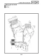
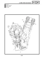
Page 58: ...2 31 LUBRICATION DIAGRAMS SPEC 1 Oil pump 2 Exhaust camshaft 3 Intake camshaft 4 Oil strainer...
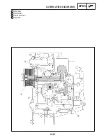
Page 59: ...2 32 LUBRICATION DIAGRAMS SPEC 1 Oil cooler 2 Oil strainer 3 Oil level switch 4 Oil pump...
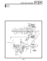
Page 60: ...2 33 LUBRICATION DIAGRAMS SPEC 1 Main axle 2 Oil pump 3 Relief valve...
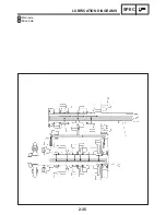
Page 62: ...2 35 LUBRICATION DIAGRAMS SPEC 1 Main axle 2 Drive axle...
Page 398: ...8 27 LIGHTING SYSTEM ELEC EAS00780 LIGHTING SYSTEM CIRCUIT DIAGRAM...
Page 405: ...8 34 SIGNALING SYSTEM ELEC EAS00793 SIGNALING SYSTEM CIRCUIT DIAGRAM...
Page 433: ...FZ6 SS FZ6 SSC WIRING DIAGRAM...
Page 435: ......


