2-41
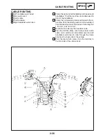
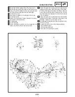
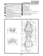
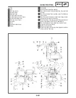
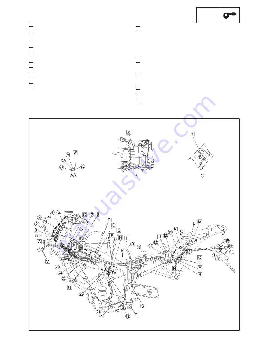
A Route the throttle cables above the stay assy 1.
B Route the main switch lead above the clutch cable.
C Line up the left handlebar switch lead coupler and
fan motor lead coupler behind the head pipe.
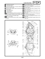
D To the main switch.
E Place three couplers on the flange of the cover.
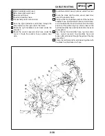
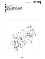
F To the fuel pump.
G Clamp four wire leads. There should be no exces-
sive slack on the wire leads.
H To the engine.
I To the fuel tank.
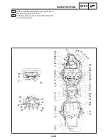
J Either installation position can be accepted, but
make sure that the leads are not crossed.
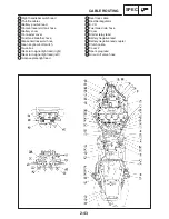
K Clamp the rear turn signal lead and license plate
light lead to the frame. Hook the clamp to the brack-
et. Pull out the lead sufficiently to the frame side and
route it along with the side of the back stay. Cut the
tip of the clamp to be between 1 and 5 mm (0.04 and
0.20 in) upward.
L Clamp the rear turn signal lead and license plate
light lead to the frame. Cut the tip of the clamp to be
between 1 and 5 mm (0.04 and 0.20 in).
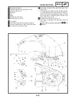
M Gap between the lead and muffler should be 10 mm
(0.39 in) or more.
N Coupler should not run on the relay assembly.
O To the tail/brake light.
P To the license plate light.
Q To the rear turn signal light. (right)
CABLE ROUTING
SPEC
Summary of Contents for FZ6-SS
Page 1: ......
Page 47: ...2 20 TIGHTENING TORQUES SPEC Cylinder head tightening sequence Crankcase tightening sequence...
Page 52: ...2 25 COOLING SYSTEM DIAGRAMS SPEC 1 Radiator 2 Oil cooler COOLING SYSTEM DIAGRAMS...
Page 53: ...2 26 COOLING SYSTEM DIAGRAMS SPEC 1 Water pump 2 Oil cooler 3 Radiator...
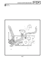
Page 54: ...2 27 COOLING SYSTEM DIAGRAMS SPEC 1 Oil cooler 2 Water pump...
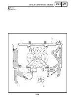
Page 55: ...2 28 COOLING SYSTEM DIAGRAMS SPEC 1 Radiator 2 Thermostat...
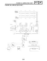
Page 56: ...2 29 ENGINE OIL LUBRICATION CHART SPEC ENGINE OIL LUBRICATION CHART...
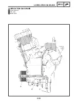
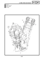
Page 58: ...2 31 LUBRICATION DIAGRAMS SPEC 1 Oil pump 2 Exhaust camshaft 3 Intake camshaft 4 Oil strainer...
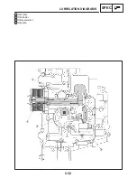
Page 59: ...2 32 LUBRICATION DIAGRAMS SPEC 1 Oil cooler 2 Oil strainer 3 Oil level switch 4 Oil pump...
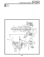
Page 60: ...2 33 LUBRICATION DIAGRAMS SPEC 1 Main axle 2 Oil pump 3 Relief valve...
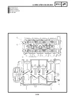
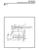
Page 62: ...2 35 LUBRICATION DIAGRAMS SPEC 1 Main axle 2 Drive axle...
Page 398: ...8 27 LIGHTING SYSTEM ELEC EAS00780 LIGHTING SYSTEM CIRCUIT DIAGRAM...
Page 405: ...8 34 SIGNALING SYSTEM ELEC EAS00793 SIGNALING SYSTEM CIRCUIT DIAGRAM...
Page 433: ...FZ6 SS FZ6 SSC WIRING DIAGRAM...
Page 435: ......

