2-47
CABLE ROUTING
SPEC
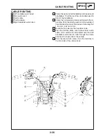
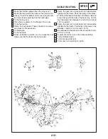
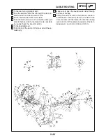
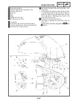
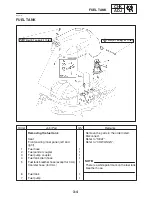
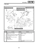
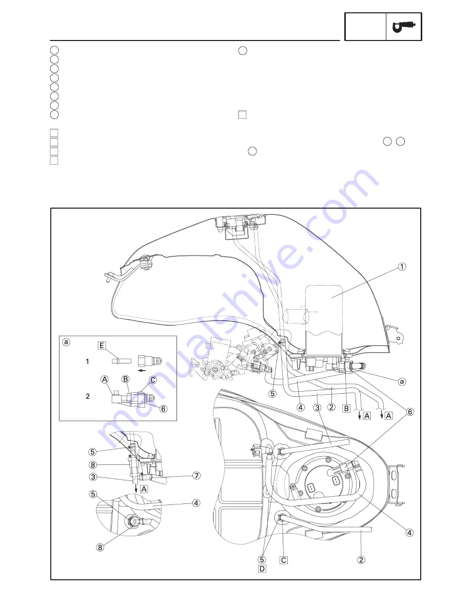
a Fuel piping connector attachment directions. (fuel
pump side)
1. It is inserted until it makes a click sound the connec-
tor, and it checks that a connector does not fail out. It
takes care that a foreign substance does not enter
into a seal portion. (Working gloves should not be
used at the time of work.)
E It prevents that this portion falls out.
2. The clamp is attached from the bottom after the
work of “1”.
It checks being completely equipped with
,
and
section.
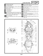
A
B
C
1
Fuel pump assembly
2
Fuel tank breather hose (except for CAL)
3
Fuel tank drain hose
4
Fuel hose
5
Clip
6
Clamp
7
Charge hose (for CAL)
8
Roll over valve (for CAL)
A Air opening.
B Install the O-ring with its lip pointed upward.
C Fuel tank breather hose has a white point mark.
D Point the knob of clip front side.
Summary of Contents for FZ6-SS
Page 1: ......
Page 47: ...2 20 TIGHTENING TORQUES SPEC Cylinder head tightening sequence Crankcase tightening sequence...
Page 52: ...2 25 COOLING SYSTEM DIAGRAMS SPEC 1 Radiator 2 Oil cooler COOLING SYSTEM DIAGRAMS...
Page 53: ...2 26 COOLING SYSTEM DIAGRAMS SPEC 1 Water pump 2 Oil cooler 3 Radiator...
Page 54: ...2 27 COOLING SYSTEM DIAGRAMS SPEC 1 Oil cooler 2 Water pump...
Page 55: ...2 28 COOLING SYSTEM DIAGRAMS SPEC 1 Radiator 2 Thermostat...
Page 56: ...2 29 ENGINE OIL LUBRICATION CHART SPEC ENGINE OIL LUBRICATION CHART...
Page 58: ...2 31 LUBRICATION DIAGRAMS SPEC 1 Oil pump 2 Exhaust camshaft 3 Intake camshaft 4 Oil strainer...
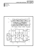
Page 59: ...2 32 LUBRICATION DIAGRAMS SPEC 1 Oil cooler 2 Oil strainer 3 Oil level switch 4 Oil pump...
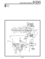
Page 60: ...2 33 LUBRICATION DIAGRAMS SPEC 1 Main axle 2 Oil pump 3 Relief valve...
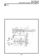
Page 62: ...2 35 LUBRICATION DIAGRAMS SPEC 1 Main axle 2 Drive axle...
Page 398: ...8 27 LIGHTING SYSTEM ELEC EAS00780 LIGHTING SYSTEM CIRCUIT DIAGRAM...
Page 405: ...8 34 SIGNALING SYSTEM ELEC EAS00793 SIGNALING SYSTEM CIRCUIT DIAGRAM...
Page 433: ...FZ6 SS FZ6 SSC WIRING DIAGRAM...
Page 435: ......

