3-17
ADJUSTING THE VALVE CLEARANCE/
SYNCHRONIZING THE THROTTLE BODIES
CHK
ADJ
NOTE:
NOTE:
NOTE:
7. Install:
S
all removed parts
For installation, reverse the removal procedure.
SYNCHRONIZING THE THROTTLE BODIES
Prior to synchronizing the throttle bodies, the
valve clearance and the engine idling speed
should be properly adjusted and the ignition tim-
ing should be checked.
1. Stand the motorcycle on a level surface.
Place the motorcycle on a suitable stand.
2. Remove:
S
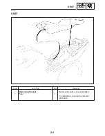
seat
Refer to “SEAT”.
S
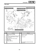
front cowling inner panel (left and right)
Refer to “COWLINGS”
S
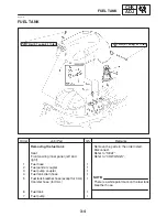
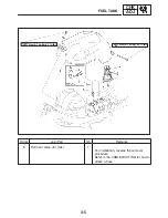
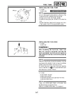
fuel tank
Refer to “FUEL TANK”.
S
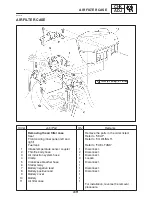
air filter case
Refer to “AIR FILTER CASE”.
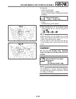
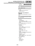
3. Install:
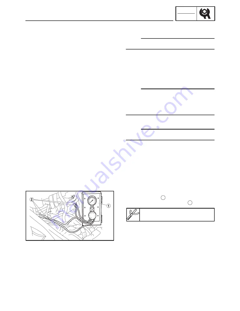
S
vacuum gauge
1
(onto the synchronizing hose
2
)
Vacuum gauge
90890-03094, YU-08030
4. Install:
S
air filter case
Refer to “AIR FILTER CASE”.
S
fuel tank
Refer to “FUEL TANK”.
S
changing the meter display.
Refer to “FEATURES” in chapter 1.
5. Start the engine and let it warm up for several
minutes.
Summary of Contents for FZ6-SS
Page 1: ......
Page 47: ...2 20 TIGHTENING TORQUES SPEC Cylinder head tightening sequence Crankcase tightening sequence...
Page 52: ...2 25 COOLING SYSTEM DIAGRAMS SPEC 1 Radiator 2 Oil cooler COOLING SYSTEM DIAGRAMS...
Page 53: ...2 26 COOLING SYSTEM DIAGRAMS SPEC 1 Water pump 2 Oil cooler 3 Radiator...
Page 54: ...2 27 COOLING SYSTEM DIAGRAMS SPEC 1 Oil cooler 2 Water pump...
Page 55: ...2 28 COOLING SYSTEM DIAGRAMS SPEC 1 Radiator 2 Thermostat...
Page 56: ...2 29 ENGINE OIL LUBRICATION CHART SPEC ENGINE OIL LUBRICATION CHART...
Page 58: ...2 31 LUBRICATION DIAGRAMS SPEC 1 Oil pump 2 Exhaust camshaft 3 Intake camshaft 4 Oil strainer...
Page 59: ...2 32 LUBRICATION DIAGRAMS SPEC 1 Oil cooler 2 Oil strainer 3 Oil level switch 4 Oil pump...
Page 60: ...2 33 LUBRICATION DIAGRAMS SPEC 1 Main axle 2 Oil pump 3 Relief valve...
Page 62: ...2 35 LUBRICATION DIAGRAMS SPEC 1 Main axle 2 Drive axle...
Page 398: ...8 27 LIGHTING SYSTEM ELEC EAS00780 LIGHTING SYSTEM CIRCUIT DIAGRAM...
Page 405: ...8 34 SIGNALING SYSTEM ELEC EAS00793 SIGNALING SYSTEM CIRCUIT DIAGRAM...
Page 433: ...FZ6 SS FZ6 SSC WIRING DIAGRAM...
Page 435: ......

