GX-900
GX-900
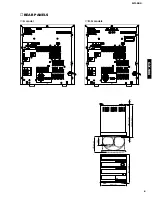
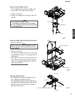
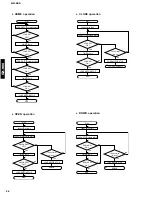
Fig. 8
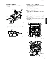
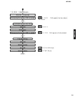
Fig. 7
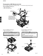
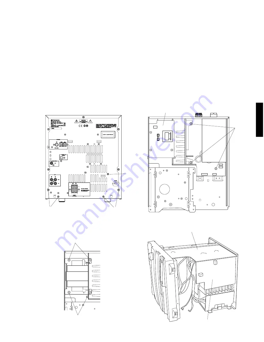
Fig. 9
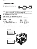
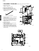
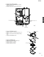
8. Operation Check of P.C.B. Main (1)
a. Remove the CD Mechanical Unit.
b. Remove the Panel Unit.
c. Remove the Deck Mechanical Unit.
d. Remove the MD Mechanical Unit.
e. Remove 5 screws (
!2
) in Fig. 7.
f. Remove 1 screw (
!3
) and then remove the P.C.B. Main (2) in Fig. 8.
g. Remove 3 screws (
!4
) in Fig. 8.
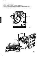
h. Remove 4 screws (
!5
) and then remove the Power Transformer in Fig. 9.
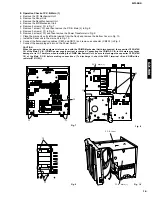
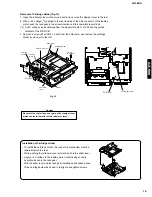
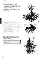
i. Place the main unit on its left side (viewed from the front) and remove the Bottom Cover in Fig. 10.
j. Install the Panel unit to the main unit in Fig. 10.
k. Connect the flat connecting cables ( CB10 and CB13 ) and remove a connector ( CB805 ) in Fig. 2.
l. Connect the power plug and turn on the Power Switch.
Fig. 10
10
!2
!2
!2
!3
!4
P.C.B. Main (2)
!5
!5
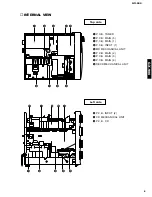
P.C.B. Input
P.C.B. Main (1)
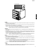
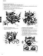
CAUTION
When the power to this equipment is turned on with the CD/MD Mechanical Unit disconnected, the capacitor C255(4700/
16) of the Main P.C.B. (CD/MD power supply section) is charged. Connecting the CD/MD P.C.B. in this state may cause
damage to its IC. Therefore, when installing the CD/MD Mechanical Unit, be sure to discharge the capacitor C255(4700/
16) of the Main P.C.B. before making connections. (To discharge it, short the W201 teB and GND with a
resistor(270
Ω
1W).)
Summary of Contents for GX-900
Page 103: ...GX 900 GX 900 ...


